Themes Unified State Exam codifier : self-induction, inductance, energy magnetic field.
Self-induction is a special case of electromagnetic induction. It turns out that the electric current in the circuit, changing over time, influences itself in a certain way.
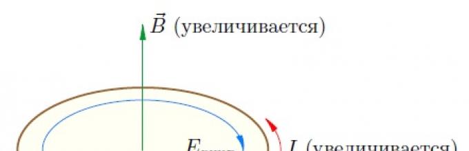
Situation 1.Suppose that the current in the circuit increases. Let the current flow counterclockwise; then the magnetic field of this current is directed upward and increases (Fig. 1).

Rice. 1. The vortex field prevents the current from increasing
Thus, our circuit finds itself in the alternating magnetic field of its own current. The magnetic field in this case increases (together with the current) and therefore generates a vortex electric field, the lines of which are directed clockwise in accordance with Lenz’s rule.
As we see, the vortex electric field is directed against the current, preventing its increase; it seems to “slow down” the current. Therefore, when any circuit is closed, the current is not established instantly - it takes some time to overcome the braking effect of the resulting vortex electric field.
Situation 2. Let us now assume that the current in the circuit decreases. The magnetic field of the current also decreases and generates a vortex electric field directed counterclockwise (Fig. 2).

Rice. 2. The vortex field maintains a decreasing current
Now the vortex electric field is directed in the same direction as the current; it maintains the current, preventing it from decreasing.
As we know, the work of an eddy electric field to move a unit positive charge around a circuit is the induced emf. Therefore we can give this definition.
The phenomenon of self-induction is that when the current in a circuit changes, an induced emf occurs in the same circuit.
As the current increases (in situation 1), the vortex electric field does negative work, braking free charges. Therefore, the induced emf in this case is negative.
When the current strength decreases (in situation 2), the vortex electric field does positive work, “pushing” free charges and preventing the current from decreasing. The induced emf in this case is also positive (it is easy to verify that the sign of the induced emf, determined in this way, is consistent with the rule for choosing the sign for the induced emf, formulated in the sheet “Electromagnetic induction”).
Inductance
We know that magnetic flux, penetrating the circuit, is proportional to the magnetic field induction: . In addition, experience shows that the magnitude of the magnetic field induction of a current-carrying circuit is proportional to the current strength: . Therefore, the magnetic flux through the surface of the circuit, created by the magnetic field of the current in this very circuit, is proportional to the current strength: .
The proportionality coefficient is designated and called inductance contour:
(1)
Inductance depends on geometric properties circuit (shape and size), as well as on the magnetic properties of the medium in which the circuit is placed (Do you catch the analogy? The capacitance of a capacitor depends on its geometric characteristics, as well as on the dielectric constant of the medium between the plates of the capacitor). The unit of measurement for inductance is Henry(Gn).
Let us assume that the shape of the circuit, its dimensions and the magnetic properties of the medium remain constant (for example, our circuit is a coil into which a core is not inserted); The change in magnetic flux through the circuit is caused only by the change in current. Then, and Faraday’s law takes the form:
(2)
Thanks to the minus sign in (2), the induced emf turns out to be negative when the current increases and positive when the current decreases, which we saw above.
Let's consider two experiments demonstrating the phenomenon of self-induction when closing and opening a circuit.

Rice. 3. Self-induction when closing the circuit
In the first experiment, two light bulbs are connected in parallel to a battery, and the second one is connected in series with a coil of sufficiently high inductance (Fig. 3).
The key is initially open.
When the key is closed, light 1 lights up immediately, and light 2 lights up gradually. The fact is that an induced emf appears in the coil, which prevents the current from increasing. Therefore, the maximum current value in the second light bulb is established only after some noticeable time after the first light bulb flashes.
This delay time is greater, the greater the inductance of the coil. The explanation is simple: after all, then the intensity of the vortex electric field arising in the coil will be greater, and therefore the battery will have to do a lot of work to overcome the vortex field that slows down the charged particles.
In the second experiment, a coil and a light bulb are connected in parallel to the battery (Fig. 4). The resistance of the coil is much less than the resistance of the light bulb.

Rice. 4. Self-induction when the circuit opens
The key is initially closed. The light bulb does not light - the voltage on it is close to zero due to the low resistance of the coil. Almost all the current flowing in an unbranched circuit passes through the coil.
When the key is opened, the light flashes brightly! Why? The current through the coil begins to decrease sharply, and a significant induced emf arises, supporting the decreasing current (after all, the induced emf, as can be seen from (2), is proportional to the rate of change of the current).
In other words, when the key is opened, a very large vortex electric field appears in the coil, accelerating free charges. Under the influence of this vortex field, a current pulse runs through the light bulb, and we see a bright flash. If the inductance of the coil is sufficiently large, the induced emf can become significantly greater than the emf of the battery, and the light bulb will completely burn out.
You may not mind the light bulb, but in industry and energy this effect is a serious problem. Since when the circuit is opened, the current begins to decrease very quickly, the induced emf arising in the circuit can significantly exceed the rated voltage and reach dangerously large values. Therefore, in units that consume high current, special hardware precautions are provided (for example, oil switches in power plants) to prevent instantaneous opening of the circuit.
Electromechanical analogy
It is not difficult to notice a certain analogy between inductance in electrodynamics and mass in mechanics.
1. It takes some time to accelerate a body to a given speed - it is not possible to instantly change the speed of a body. With a constant force applied to the body, this time is longer, the more more mass bodies.
It takes some time for the current in the coil to reach its maximum value; the current is not established instantly. The greater the inductance of the coil, the greater the current settling time.
2. If a body hits a stationary wall, then the speed of the body decreases very quickly. The wall takes the blow, and its destructive effect is stronger, the greater the body mass.
When the circuit with the coil is opened, the current decreases very quickly. The circuit takes a “blow” in the form of a vortex electric field generated by the decreasing magnetic field of the current, and this “blow” is stronger, the greater the inductance of the coil. The induced emf can reach such large values that a breakdown of the air gap will damage the equipment.
In fact these electromechanical analogies extend quite far; they concern not only inductance and mass, but also other quantities, and turn out to be very useful in practice. We will talk about this more in the leaflet about electromagnetic vibrations.
Magnetic field energy
Let us recall the second experiment with a light bulb that does not light when the key is closed and flashes brightly when the circuit is opened. We directly observe that after the switch is opened, energy is released in the light bulb. But where does this energy come from?
It comes, of course, from the coil - nowhere else. But what kind of energy was stored in the coil and how to calculate this energy? To understand this, let's continue our electromechanical analogy between inductance and mass.
To accelerate a body of mass from rest to speed, external force must do the work. The body acquires kinetic energy, which is equal to the work expended: .
In order for the current in the inductor to reach a value after closing the circuit, the current source must do work to overcome the vortex electric field directed against the current. The work of the source is used to create a current and is converted into the energy of the magnetic field of the created current. This energy is stored in the coil; It is this energy that is then released in the light bulb after the key is opened (in the second experiment).
Inductance serves as an analogue to mass; current is an obvious analogue of speed. Therefore, it is natural to assume that for the energy of the magnetic field of the coil there may be a formula similar to the expression for kinetic energy:
(3)
(especially since the right side of this formula has the dimension of energy - check!).
Formula (3) indeed turns out to be true. It is not necessary to be able to derive it yet, but if you know what an integral is, then it will not be difficult for you to understand the following reasoning.
Let in this moment The current through the coil is equal to . Let's take a short period of time. During this interval, the increment in current strength is equal to; the value is considered so small that it is much less than .
Over time, a charge passes through the circuit. The vortex electric field does negative work:
The current source does the same positive work in absolute value (remember, we neglect the coil resistance, so all the work of the source is done against the vortex field):
Integrating this from zero to , we find the work of the source, which is spent on creating the current:
This work is converted into the energy of the magnetic field of the created current, and we arrive at formula (3).
When the switch is closed in the circuit shown in Figure 1, it will occur, the direction of which is shown by single arrows. With the advent of current, a current arises, the induction lines of which cross the conductor and induce emf in it. As stated in the article “The phenomenon of electromagnetic induction”, this EMF is called self-induction EMF. Since any induced emf is directed against the cause that caused it, and this cause will be the emf of the battery of elements, the self-induction emf of the coil will be directed against the emf of the battery. The direction of self-induction EMF in Figure 1 is shown by double arrows.
Thus, the current is not established in the circuit immediately. Only when established, the intersection of the conductor magnetic lines will stop and the self-induced emf will disappear. Then the circuit will leak.
Figure 2 shows graphic image direct current. The horizontal axis represents time, and the vertical axis represents current. It can be seen from the figure that if at the first moment of time the current is 6 A, then at the third, seventh and so on moments of time it will also be equal to 6 A.
Figure 3 shows how the current is established in the circuit after switching on. The self-induction emf, directed at the moment of switching on against the emf of the battery of elements, weakens the current in the circuit, and therefore at the moment of switching on the current is zero. Then, at the first moment of time, the current is 2 A, at the second moment of time - 4 A, at the third - 5 A, and only after some time a current of 6 A is established in the circuit.
 |  |
| Figure 3. Graph of current increase in the circuit taking into account the self-inductive emf | Figure 4. The self-induction emf at the moment of opening the circuit is directed in the same direction as EMF source voltage |
When the circuit is opened (Figure 4), the disappearing current, the direction of which is shown by a single arrow, will reduce its magnetic field. This field, decreasing from a certain value to zero, will again cross the conductor and induce a self-induction emf in it.
When turning off the electrical circuit with EMF inductance self-induction will be directed in the same direction as the EMF of the voltage source. The direction of the self-induction EMF is shown in Figure 4 by a double arrow. As a result of the action of self-induction emf, the current in the circuit does not disappear immediately.
Thus, the self-induced emf is always directed against the cause that caused it. Noting this property, they say that the self-induction EMF is reactive in nature.
Graphically, the change in current in our circuit, taking into account the self-inductive emf when it is closed and when it is subsequently opened at the eighth moment in time, is shown in Figure 5.
 |  |
| Figure 5. Graph of the rise and fall of the current in the circuit, taking into account the self-induction emf | Figure 6. Induction currents when the circuit is opened |
When opening circuits containing a large number of turns and massive steel cores or, as they say, having high inductance, the self-inductive emf can be many times greater than the emf of the voltage source. Then, at the moment of opening, the air gap between the knife and the fixed clamp of the switch will be broken and the resulting electric arc will melt the copper parts of the switch, and if there is no casing on the switch, it can burn a person’s hands (Figure 6).
In the circuit itself, the self-induction EMF can break through the insulation of the turns of the coils, and so on. To avoid this, some switching devices provide protection against self-induction EMF in the form of a special contact that short-circuits the electromagnet winding when switched off.
It should be taken into account that the self-induction EMF manifests itself not only at the moments when the circuit is turned on and off, but also during any changes in current.
The magnitude of the self-induction emf depends on the rate of change of current in the circuit. So, for example, if for the same circuit in one case within 1 second the current in the circuit changed from 50 to 40 A (that is, by 10 A), and in another case from 50 to 20 A (that is, by 30 A ), then in the second case a threefold greater self-induction emf will be induced in the circuit.
The magnitude of the self-inductive emf depends on the inductance of the circuit itself. Circuits with high inductance are the windings of generators, electric motors, transformers and induction coils with steel cores. Straight conductors have lower inductance. Short straight conductors, incandescent lamps and electric heating devices (stoves, stoves) have practically no inductance and the appearance of self-inductive emf in them is almost not observed.
The magnetic flux penetrating the circuit and inducing the self-induction emf in it is proportional to the current flowing through the circuit:
F = L × I ,
Where L- proportionality coefficient. It's called inductance. Let us determine the dimension of inductance:
![]()
Ohm × sec is otherwise called henry (Hn).
1 henry = 10 3 ; millihenry (mH) = 10 6 microhenry (µH).
Inductance, except Henry, is measured in centimeters:
1 henry = 10 9 cm.
For example, 1 km of telegraph line has an inductance of 0.002 H. The inductance of the windings of large electromagnets reaches several hundred henries.
If the loop current changes by Δ i, then the magnetic flux will change by the value Δ Ф:
Δ Ф = L × Δ i .
The magnitude of the self-induction EMF that appears in the circuit will be equal to (formula of the self-induction EMF):
![]()
If the current changes uniformly over time, the expression will be constant and can be replaced by the expression. Then absolute value The self-induced emf arising in the circuit can be found as follows:
Based on the last formula, we can define the unit of inductance - henry:
A conductor has an inductance of 1 H if, with a uniform change in current by 1 A per 1 second, a self-inductive emf of 1 V is induced in it.
As we saw above, self-inductive emf occurs in a direct current circuit only at the moments of its switching on, switching off, and whenever it changes. If the circuit is unchanged, then the magnetic flux of the conductor is constant and the self-induction emf cannot arise (since . At moments of current change in the circuit, the self-induction emf interferes with changes in the current, that is, it provides a kind of resistance to it.
Often in practice there are cases when it is necessary to make a coil that does not have inductance (additional resistance to electrical measuring instruments, resistance of plug rheostats, and the like). In this case, a bifilar coil winding is used (Figure 7)
As is easy to see from the drawing, in adjacent conductors currents flow in opposite directions. Consequently, the magnetic fields of neighboring conductors cancel each other out. The total magnetic flux and inductance of the coil will be zero. To further understand the concept of inductance, let us give an example from the field of mechanics.
As is known from physics, according to Newton’s second law, the acceleration received by a body under the influence of a force is proportional to the force itself and inversely proportional to the mass of the body:
![]()
Let's compare the last formula with the formula for self-induced emf, taking the absolute value of the emf:
If in these formulas changes in speed over time are compared to changes in current over time, mechanical force- electromotive force of self-induction, then the body mass will correspond to the inductance of the circuit.
With uniform straight motion a= 0, so F= 0, that is, if no forces act on the body, its motion will be rectilinear and uniform (Newton’s first law).
In DC circuits, the current value does not change and therefore e L = 0.
The term induction in electrical engineering means the occurrence of current in an electrical closed circuit if it is in a changing state. Discovered only two hundred years ago by Michael Faraday. This could have been done much earlier by Andre Ampere, who conducted similar experiments. He inserted a metal rod into the coil, and then, bad luck, he went into another room to look at the galvanometer needle - what if it moved. And the arrow regularly did its job - it deviated, but while Ampere wandered through the rooms, it returned to the zero mark. This is how the phenomenon of self-induction waited for another ten years until the coil, the device and the researcher were simultaneously in the right place.
The main point of this experiment was that induced emf occurs only when the magnetic field passing through a closed loop changes. But you can change it as you like - either change the magnitude of the magnetic field itself, or simply move the source of the field relative to the same closed loop. The emf that arises in this case is called “mutual inductive emf.” But this was only the beginning of discoveries in the field of induction. Even more surprising was the phenomenon of self-induction, which was discovered around the same time. In his experiments, it was discovered that the coils not only induced a current in another coil, but also when the current in this coil changed, it induced an additional EMF in it. This is what they called the self-induced emf. Of great interest is the direction of the current. It turned out that in the case of self-induction EMF, its current is directed against its “parent” - the current caused by the main EMF.
Is it possible to observe the phenomenon of self-induction? As they say, nothing is simpler. Let's assemble the first two - a series-connected inductor and a light bulb, and the second - only the light bulb. Let's connect them to the battery via a common switch. When you turn it on, you can see that the light bulb in the circuit with the coil lights up “reluctantly,” and the second light bulb, which is faster “on the rise,” turns on instantly. What's happening? In both circuits, after switching on, current begins to flow, and it changes from zero to its maximum, and it is precisely the change in current that the inductor waits for, which generates the self-induction emf. There is an EMF and a closed circuit, which means there is also its current, but it is directed opposite to the main current of the circuit, which will eventually reach a maximum value determined by the parameters of the circuit and stop growing, and since there is no change in the current, there is no self-induction EMF. It's simple. A similar picture, but “exactly the opposite,” is observed when the current is turned off. True to her “ bad habit” to counteract any change in current, the self-induced emf maintains its flow in the circuit after the power is turned off.
The question immediately arose - what is the phenomenon of self-induction? It was found that the self-induction EMF is affected by the rate of change of current in the conductor, and can be written:
From this it can be seen that the self-induction EMF E is directly proportional to the rate of change of current dI/dt and the proportionality coefficient L, called inductance. For his contribution to the study of the question of what the phenomenon of self-inductance consists of, George Henry was rewarded by the fact that the unit of measurement of inductance, Henry (H), bears his name. It is the inductance of the current flow circuit that determines the phenomenon of self-induction. One can imagine that inductance is a kind of “storage” of magnetic energy. If the current in the circuit increases Electric Energy is converted into magnetic energy, delays the increase in current, and when the current decreases, the magnetic energy of the coil is converted into electrical energy and maintains the current in the circuit.
Probably everyone has seen a spark when turning off a plug from a socket - this is the most common manifestation of self-induction EMF in real life. But in everyday life, currents open at a maximum of 10-20 A, and the opening time is about 20 ms. With an inductance of the order of 1 H, the self-induction emf in this case will be equal to 500 V. It would seem that the question of what the phenomenon of self-induction consists of is not so complicated. But in fact, self-induced emf is a big technical problem. The bottom line is that when the circuit breaks, when the contacts have already separated, self-induction maintains the flow of current, and this leads to burnout of the contacts, because In technology, circuits with currents of hundreds and even thousands of amperes are switched. Here we are often talking about a self-inductive emf of tens of thousands of volts, and this requires additional solutions to technical issues related to overvoltages in electrical circuits.
But not everything is so gloomy. It happens that this harmful EMF is very useful, for example, in internal combustion engine ignition systems. Such a system consists of an inductor in the form of an autotransformer and a chopper. A current is passed through the primary winding, which is turned off by a breaker. As a result of an open circuit, a self-inductive emf of hundreds of volts occurs (while the battery provides only 12V). Then this voltage is further transformed, and a pulse of more than 10 kV is sent to the spark plugs.
An electric current passing through a circuit creates a magnetic field around it. The magnetic flux Φ through the circuit of this conductor (it is called own magnetic flux) is proportional to the induction module B of the magnetic field inside the circuit \(\left(\Phi \sim B \right)\), and the magnetic field induction in turn is proportional to the current strength in the circuit \(\left(B\sim I \right)\ ).
Thus, the own magnetic flux is directly proportional to the current strength in the circuit \(\left(\Phi \sim I \right)\). This relationship can be represented mathematically as follows:
\(\Phi = L \cdot I,\)
Where L- proportionality coefficient, which is called circuit inductance.
- Loop inductance- scalar physical quantity, numerically equal to the ratio own magnetic flux penetrating the circuit to the current strength in it:
The SI unit of inductance is the henry (H):
1 H = 1 Wb/(1 A).
- The inductance of the circuit is 1 H if, at a direct current of 1 A, the magnetic flux through the circuit is 1 Wb.
The inductance of the circuit depends on the size and shape of the circuit, on the magnetic properties of the environment in which the circuit is located, but does not depend on the current strength in the conductor. Thus, the inductance of the solenoid can be calculated using the formula
\(~L = \mu \cdot \mu_0 \cdot N^2 \cdot \dfrac(S)(l),\)
Where μ is the magnetic permeability of the core, μ 0 is the magnetic constant, N- number of solenoid turns, S- coil area, l- solenoid length.
With the shape and dimensions of a fixed circuit remaining unchanged, the intrinsic magnetic flux through this circuit can change only when the current strength in it changes, i.e.
\(\Delta \Phi =L \cdot \Delta I.\) (1)
Self-induction phenomenon
If a direct current passes through a circuit, then there is a constant magnetic field around the circuit, and the intrinsic magnetic flux passing through the circuit does not change over time.
If the current passing in the circuit changes over time, then the correspondingly changing own magnetic flux, and, according to the law of electromagnetic induction, creates an EMF in the circuit.
- The occurrence of induced emf in a circuit, which is caused by a change in current strength in this circuit, is called self-induction phenomenon.
Self-induction was discovered by the American physicist J. Henry in 1832. I The emf that appears in this case is the self-induction emf E si. The self-induction emf creates a self-induction current in the circuit
si.
The direction of the self-induction current is determined by Lenz's rule: the self-induction current is always directed so that it counteracts the change in the main current. If the main current increases, then the self-induction current is directed against the direction of the main current; if it decreases, then the directions of the main current and the self-induction current coincide. L Using the law of electromagnetic induction for an inductive circuit
and equation (1), we obtain the expression for the self-induction emf:
- \(E_(si) =-\dfrac(\Delta \Phi )(\Delta t)=-L\cdot \dfrac(\Delta I)(\Delta t).\) I The self-induction emf is directly proportional to the rate of change of current in the circuit, taken with the opposite sign.< 0), т.е. This formula can only be used with a uniform change in current strength. With increasing current (Δ I < 0), ЭДС положительная (E si >> 0), negative EMF (E si
induced current
directed in the opposite direction of the source current.
- When the current decreases (Δ 0), i.e. the induced current is directed in the same direction as the source current.
From the resulting formula it follows that \(L=-E_(si) \cdot \dfrac(\Delta t)(\Delta I).\) Inductance L. When the key is closed, the first lamp flashes almost immediately, and the second with a noticeable delay. This is explained by the fact that in the section of the circuit with the lamp 1 there is no inductance, so there will be no self-induction current, and the current in this lamp almost instantly reaches its maximum value. In the area with the lamp 2 when the current in the circuit increases (from zero to maximum), a self-induction current appears Isi, which prevents the rapid increase in current in the lamp. Figure 2 shows an approximate graph of current changes in the lamp 2 when the circuit is closed.
When the key is opened, the current in the lamp 2 will also fade slowly (Fig. 3, a). If the inductance of the coil is large enough, then immediately after opening the switch there may even be a slight increase in current (lamp 2 flares up more strongly), and only then the current begins to decrease (Fig. 3, b).
 Rice. 3
 The phenomenon of self-induction creates a spark at the point where the circuit opens. If there are powerful electromagnets in the circuit, the spark can turn into an arc and damage the switch. To open such circuits, power plants use special switches.
Magnetic field energy
Magnetic field energy of an inductor circuit L with current strength I
\(~W_m = \dfrac(L \cdot I^2)(2).\)
Since \(~\Phi = L \cdot I\), the energy of the magnetic field of the current (coil) can be calculated knowing any two of the three values ( Φ, L, I):
\(~W_m = \dfrac(L \cdot I^2)(2) = \dfrac(\Phi \cdot I)(2)=\dfrac(\Phi^2)(2L).\)
The magnetic field energy contained in a unit volume of space occupied by the field is called volumetric energy density magnetic field:
\(\omega_m = \dfrac(W_m)(V).\)
*Derivation of the formula
1 output.
Let's connect a conducting circuit with inductance to a current source L. Let the current increase uniformly from zero to a certain value over a short period of time Δt I (Δ I = I). The self-induction emf will be equal to
\(E_(si) =-L \cdot \dfrac(\Delta I)(\Delta t) = -L \cdot \dfrac(I)(\Delta t).\)
Over a given period of time Δ t charge is transferred through the circuit
\(\Delta q = \left\langle I \right \rangle \cdot \Delta t,\)
where \(\left \langle I \right \rangle = \dfrac(I)(2)\) is the average current value over time Δ t with its uniform increase from zero to I.
Current strength in a circuit with inductance L reaches its value not instantly, but over a certain finite period of time Δ t. In this case, a self-inductive emf E si arises in the circuit, preventing the increase in current strength. Consequently, when the current source is closed, it does work against the self-inductive emf, i.e.
\(A = -E_(si) \cdot \Delta q.\)
The work expended by the source to create current in the circuit (without taking into account thermal losses) determines the magnetic field energy stored by the current-carrying circuit. That's why
\(W_m = A = L \cdot \dfrac(I)(\Delta t) \cdot \dfrac(I)(2) \cdot \Delta t = \dfrac(L \cdot I^2)(2).\ )
2 output.
If the magnetic field is created by the current passing in the solenoid, then the inductance and modulus of the magnetic field of the coil are equal
\(~L = \mu \cdot \mu_0 \cdot \dfrac (N^2)(l) \cdot S, \,\,\, ~B = \dfrac (\mu \cdot \mu_0 \cdot N \cdot I)(l)\)
\(I = \dfrac (B \cdot l)(\mu \cdot \mu_0 \cdot N).\)
Substituting the resulting expressions into the formula for the magnetic field energy, we obtain
\(~W_m = \dfrac (1)(2) \cdot \mu \cdot \mu_0 \cdot \dfrac (N^2)(l) \cdot S \cdot \dfrac (B^2 \cdot l^2) ((\mu \cdot \mu_0)^2 \cdot N^2) = \dfrac (1)(2) \cdot \dfrac (B^2)(\mu \cdot \mu_0) \cdot S \cdot l. \)
Since \(~S \cdot l = V\) is the volume of the coil, the magnetic field energy density is equal to
\(\omega_m = \dfrac (B^2)(2\mu \cdot \mu_0),\)
Where IN- magnetic field induction module, μ - magnetic permeability of the medium, μ 0 - magnetic constant.
Literature
- Aksenovich L. A. Physics in high school: Theory. Tasks. Tests: Textbook. benefits for institutions providing general education. environment, education / L. A. Aksenovich, N. N. Rakina, K. S. Farino; Ed. K. S. Farino. - Mn.: Adukatsiya i vyhavanne, 2004. - P. 351-355, 432-434.
- Zhilko V.V. Physics: textbook. allowance for 11th grade. general education institutions with Russian language 12-year studies (basic and elevated levels) / V.V. Zhilko, L.G. Markovich. - Mn.: Nar. Asveta, 2008. - pp. 183-188.
- Myakishev, G.Ya. Physics: Electrodynamics. 10-11 grades : textbook For in-depth study physics / G.Ya. Myakishev, A.3. Sinyakov, V.A. Slobodskov. - M.: Bustard, 2005. - P. 417-424.
>> Self-induction. Inductance
§ 15 SELF-INDUCTION. INDUCTANCE
Self-induction. If the reel goes alternating current, then the magnetic flux passing through the coil changes. Therefore, in the same conductor through which alternating current flows, an induced emf occurs. This phenomenon is called self-induction.
During self-induction, the conducting circuit performs double role: Alternating current in a conductor causes a magnetic flux to appear across the surface bounded by the loop. And since the magnetic flux changes over time, an induced emf appears. According to Lenz's rule, at the moment the current increases, the intensity of the vortex electric field is directed against the current. Consequently, at this moment the vortex field prevents the current from increasing. On the contrary, at the moment the current decreases, the vortex field supports it.

The phenomenon of self-induction can be observed in simple experiments. Figure 2.13 shows a diagram of a parallel connection of two identical lamps. One of them is connected to the source through a resistor R, and the other in series with a coil L equipped with an iron core.
When the key is closed, the first lamp flashes almost immediately, and the second with a noticeable delay. The self-induction emf in the circuit of this lamp is high, and the current strength does not immediately reach its maximum value (Fig. 2.14).

The appearance of self-inductive emf upon opening can be observed in an experiment with a circuit schematically shown in Figure 2.15. When the switch is opened, a self-induction emf appears in coil L, maintaining the initial current. as a result, at the moment of opening, a current flows through the galvanometer (colored arrow), directed opposite the initial current before opening (black arrow). The current when the circuit is opened can exceed the current passing through the galvanometer when the switch is closed. This means that the self-induction emf is greater than the emf of the battery of cells.
Lesson content lesson notes supporting frame lesson presentation acceleration methods interactive technologies Practice tasks and exercises self-test workshops, trainings, cases, quests homework discussion questions rhetorical questions from students Illustrations audio, video clips and multimedia photographs, pictures, graphics, tables, diagrams, humor, anecdotes, jokes, comics, parables, sayings, crosswords, quotes Add-ons abstracts articles tricks for the curious cribs textbooks basic and additional dictionary of terms other Improving textbooks and lessonscorrecting errors in the textbook updating a fragment in a textbook, elements of innovation in the lesson, replacing outdated knowledge with new ones Only for teachers perfect lessons calendar plan for a year guidelines discussion programs Integrated Lessons