In 3d max, you can create a polygon in a specific location on the polygonal mesh in different ways:
Frame highlight, cover
If the area is closed, it is "frame-lid". Select the selection with a frame (border), select the closed area into which you want to insert the polygon and press the "Cap" button (lid), thereby closing the selected frame with a lid. If you cannot select an area with a frame, then it is not closed, i.e. closed only visually.
This is perhaps the easiest way to create a polygon in a polygon mesh.
Boxing, joining
Select the border between the two areas between which there should be a connection and select the “Connect” operation by clicking on the button of the same name in the “Object type” area in the “Compound objects” list. The necessary polygons will be created between the selected areas.
Bridge
If there are two non-touching edges, then a “bridge” is what you need. You select 2 unconnected edges, the Bridge command creates a polygon between them.
Creation
Press the "Create" button and go through all the points (select counterclockwise) between which you need to create a polygon.
Manual creation
Manually creating a polygon using any convenient method will come to the rescue when the above methods do not work. The easiest way to create new polygons is to move the edge away with the Shift key held down, followed by the usual “soldering/welding” of points.
Welding
You need to select the necessary points to connect into one and use the “Weld” (weld) or “Target Weld” command, which is the most convenient and smooth.
PolyBoost
PolyBoost has a button "Create a polygon between selected points". This is, of course, if there is PolyBoost.
Purpose of the work: introduction to the principles of polygonal modeling in the 3D Studio Max program.General information
Polygon modeling (mesh editing or wireframe editing) is low-level modeling and is based on manipulating the vertices, edges and faces of objects (Fig. 1).
Figure 1. Components of any polygonal object.
Polygonal modeling is one of the main modeling methods. With polygonal modeling, the shape of an object is changed, directly affecting its components. To provide this type of modeling in 3D Studio Max, the following are used:
- objects of type Editable Mesh. Mesh can be translated as a loop, a cell of a network (lattice), therefore the object itself can be translated as “Editable Grid” or “Editable Frame”. Object Editable Mesh can be obtained using conversion, as well as the stack folding operation.
- modifier Edit Mesh(Editing Mesh (Editing Wireframe)).
Selecting subobjects
The face is a triangle, usually two triangular faces lie in the same plane and are combined into a rectangular face. To go to the subobject editing level, do the following:Step 1. Click the button Sub-Object(Subobject).
Step 2. Select a level from the object's pop-up menu.
Step 3. Use the buttons in the scroll Selection(Choice):
– level of vertices;
– rib level;
– level of triangular faces;
– level of rectangular faces;
The purpose of the mesh editing (frame editing) tools shown in Figure 2 is described in Table 1.
 Figure 2. Tools for working with an editable mesh (editable wireframe).
Table 1: Purpose of mesh editing tools (frame editing):
|
Name |
Level: V – vertex, Edg – edge, F – triangular face, Poly – face. | Purpose of the button | |
| Adding elements. | |||
| Removing elements. | |||
| Attaching other (independent) (Attach List) scene objects. Objects of other types are automatically converted to Mesh objects. | |||
| Separation of subobjects with the creation of an independent object based on them. A dialog box appears where you need to enter a name; the Detach as Clone checkbox allows you to separate not the subobject itself, but its copy. | |||
|
Divide, Break | The Divide operation divides a subobject into two parts. The Break operation splits the selected vertices so that none of them belongs to more than one edge. |
||
| Rotate the selected face by 90° to form two triangular faces based on it, where this face is common. |
|||
| Extruding subobjects. The amount of extrusion is entered in the adjacent field. | |||
|
Chamfer, Bevel | The Chamfer button allows you to create a chamfer based on selected subobjects. Bevel allows you to tighten or expand the selected population. |
||
|
SlicePlane | Setting an auxiliary plane for the Slice operation. | ||
| New elements are created at the intersection of the plane and the object. | |||
| The tool allows you to manually create new edges and cut a face by adding an edge. When the Split check box is selected, two vertices are created at the ends of the edge split points. Selecting the Refine Ends checkbox causes the adjacent faces to be split, to prevent unnecessary holes. |
|||
|
Selected | The tool allows you to remove vertices by approximating them into one averaged common one (merging); the boundary (the minimum distance between vertices at which merging begins to take effect) is specified nearby. The operation is applied to the selected set of vertices. |
||
| The button action is similar to Selected, but the user selects the average point himself (the value in the next located field specifies the maximum distance between the mouse pointer and the target at which merging occurs). |
|||
We continue to analyze the mesh editor “Edit Poly”. Let's look at the “Edit Vertices” tab during the “Vertex” (“Vertex”) mode, 3d Max vertex - the vertices of the polygons. All Edit Poly editor parameters in this tab are valid only for this mode; when switching to another, they will be unavailable.
3d max vertex.
Let's consider only the most necessary commands for editing the model mesh using “Vertex” vertices. Let me remind you that selected vertices can be moved “Move”, rotated “Rotate”, scaled “Scale”, when selecting one vertex - only move.
1. Edit Vertices scroll.
To enable 3d Max vertices click on the button  or hotkey "1". Next, look at the expanded scroll “Edit Vertices”;

2. Remove.
The “Remove” command removes a vertex and its edges. If you simply delete it with the “Del” button, then all the polygons touching this vertex will disappear;

3. Break.
Command “Break” - breaks all the vertices of the polygons at a given point. For clarity, I moved all the vertices to the sides;

4. Extrude.
The “Extrude” command of the “Edit Poly” editor extrudes a pyramid at a given point, the number of faces of which depends on the number of edges intersecting at a given vertex;

5. Weld.
The "Weld" command is one of the key operations during the 3d Max vertex editing mode.
Using the “Weld” command, you can combine groups large number peaks If, for example, you modeled a complex object in two parts separately and it’s time to stitch them into one model, then the “ Weld" command will greatly simplify this task for you.
The vertices are merged depending on the parameter value you specify. If the distance between vertices is below this value, the vertices will be merged. So it is necessary to place in advance those vertices that are combined with each other, closer to each other relative to all other selected vertices;


6. Chamfer.
Command “Chamfer” - makes a bevel on the selected vertex;


7. Target Weld.
The “Target Weld” command combines vertices in the same way as the “Weld” command, although you can only merge 2 vertices at a time. It is convenient to use in cases where there are few vertices and the distances between them are greater in relation to other vertices in the mesh.

8.Connect.
Command “Connect” - connects 2 vertices with an edge.

So, let's summarize. In this article we learned:
What is 3d max vertex (3d max vertex);
We examined the basic operations with vertices and where they can be applied;
The main command has been identified: “Weld”.
This 3ds Max polygon modeling tutorial covers the most commonly used 3d operations when using the Edit Poly modifier (or Editable Poly). This method is great for creating almost any object in 3ds Max.
First, let's create a simple Box primitive with the proportions of a real TV. 

Fig.1. Created the initial 3d primitive - Box
Let's apply a modifier to our box Edit Poly

Fig.2. Modifier applied Edit Poly
By pressing a key F4 On the keyboard in 3ds Max we turn on the display of the edges of our polygonal model.
In the modifier stack, we go to the polygon level to start modeling. And select the front polygon where we will start creating the screen. 

Fig.3. We went to the polygon level and selected the front one in the perspective window
Apply the operation to the selected polygon Inset to create a face as shown in the figure. It will serve as the basis for creating the screen. 


Fig.4. Applying the operation to the polygon Inset
We press the resulting polygon inward with the command Extrude.


Fig.5. Pressed the landfill with an operation Extrude
We subdivide the double-pressed polygon using the operation Tessellate(Subdivision), thereby increasing the detail of the front face to allow for further deformation. In general, it is not recommended to abuse this operation in your models. 


Fig.6. We increase the detail of a face using an operation Tessellate
Go to the vertex level and select the central vertex of the screen. 

Fig.7. Selected central vertex
Activate soft selection mode Soft Selection(Thanks to it, we will be able to deform the object more smoothly). Pay attention to the Falloff and Bubble options. Falloff is responsible for the width of the capture zone of neighboring vertices. Bubble- for the form of distribution of weights. The coloration clearly shows the degree of capture.
Now let's move the central vertex forward a little to round out the screen. When finished, be sure to exit soft selection mode. 


Fig.8. Move the central vertex a little forward in soft selection mode
The screen is ready, now we need to prepare the back wall. Go back to the polygon level and select the back face. 
Fig.9. Selected the back edge of the TV
Apply the operation to the selected polygon Bevel(Bevel extrusion).
Height- amount of extrusion
Outline- degree of narrowing 


Fig. 10. Selected the back edge of the TV
We extrude the back edge again using the operation Extrude.
Height- amount of extrusion 

For example, create a Box primitive of any size. Set the Length, Width and Height parameters to 3:


Now all that remains is to convert the model into an editable polygon. (Right-click on the object and select Convert To:-Editable Poly from the list that opens). At this point the preparatory part is completed and you can move on to learning the tools.
Working with vertices
First of all, in the Selection tab, click on the Vertex button (hotkey 1) to start working with the vertices of the model:

After this, you will see blue dots on the model, these are nothing more than vertices.

Try selecting any of the vertices and moving it using the Move tool:

Notice how the edges moved along with the vertex. Remember that intersecting faces are connected by vertices, and moving one vertex affects the movement of all adjacent faces.
To select multiple vertices, hold down the Ctrl key:

You have learned how to select and move vertices, now let’s look at the tools for editing vertices. All tools for working with vertices are conveniently distributed across tabs, which we will now examine. The Soft Selection tab is described in detail in the Editable Poly lesson, so we will immediately move on to the Edit Vertices tab.
Edit Vertices Tab

Remove– delete the selected vertex:

Please note that along with the vertex, the edges intersecting it were also removed. This is an important point that you should consider when modeling.
Break– allows you to separate adjacent faces that converge at the selected vertex, while adding one new vertex to each face. For example, select any vertex and press Break. It will seem to you that nothing happened, but it only seems so. Select the Move tool and try moving the vertex in any direction:

Notice that the vertex no longer moves the faces. Using the Break button, the vertex was broken into several separate vertices, creating a “hole” in the object.
Extrude– extrude a subordinate object. Most often used for extruding polygons (See in this lesson). As an example, in the corner of the object, select a vertex and click on the icon that is located to the right of the Extrude button:

Weld- merge vertices. used to combine several vertices into one. For example, select two vertices and click on the icon to the right of the Weld button. In the field that appears, enter a value at which two vertices will merge into one:

Chamfer- allows you to replace a vertex with a polygon, faces with new vertices:

Target Weld– similar to the Weld team. When using Target Weld, you can select a vertex and drag it onto another, thereby linking them into one:

add a new edge between opposite vertices:

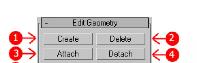
We've sorted out the tools of the Edit Vertices tab. Now let's look at the Edit Geometry tab.
Edit Geometry Tab
Create- adding a new vertex
Collapse– the command is similar to Weld and connects two vertices into one. It differs in that it can connect vertices at any distance without any numerical values.
Attach– this command works the same for all subordinate objects. Allows you to attach any new objects to this editable polygon. The attached objects will automatically turn into an editable polygon:

Slice Plane– cuts an object along a plane. By clicking the Slice Pline button, a yellow container will appear on the object, which indicates the location of the cut. This container can be moved and rotated using the transformation tools. To create a slice, you need to click on the Slice button, which is located a little lower:

To reset the default values, click the Reset Plane button. To exit the slicing mode, press the Slice Pline button again.
QuickSlice- cuts the object, thereby adding new vertices, faces and polygons. Rarely used in modeling. For example, click on this button and create a section:

Cut- a handy tool that allows you to add new edges anywhere:

Working with edges (faces)
Now go to face editing mode (key 2 on the keyboard).

An edge is a line that connects vertices. As a matter of fact, ribs can be either open or closed. To select edges, it is convenient to use the Ring and Loop buttons, which are located in the Select tab:

Try selecting any face and clicking the Ring button, you will notice how all the parallel edges are highlighted:

The Loop command selects edges that lie in the same plane:

Just like vertices, you can select multiple edges. To do this, you need to hold down the Ctrl key. Let's move on to learning the edge editing tools.
Edit Edges Tab

Insert Vertex– creation of new vertices on edges. If an edge is selected and this button is pressed, a vertex will be created at the center:

Remove– delete the selected edge:

Split– splits an edge into two parts by its vertex.
Extrude- extrude the face and then add polygons:

Weld- connects two edges.
Chamfer– adding chamfers:

Bridge- if you select two edges and click on this button, they will be united by a new polygon.
Connect– adds new ribs. For example, select two parallel edges and click this button:

Edit Geometry Tab
Create- adding a new edge.
Collapse- connect the selected edges.