1. Introduction
2. general characteristics Sulfuric acid production
3. Raw Sources of Sulfuric Acid
4.Short description Industrial methods for producing sulfuric acid
5. Selection of catalyst
6. Justification of the production method
7. Stages and process chemistry
8. Thermodynamic analysis
9. Kinetics of the oxidation process SO 2
10. Condensation of sulfuric acid
11. Thermodynamic analysis of the condensation process
12. Description of the process scheme
13. Calculation of the material balance
14. Calculation of the heat balance
15. Calculation of the contact apparatus
16. Safety measures during the operation of the production facility
17. List of references
1. Introduction
Sulfuric acid is one of the main multi-dinner products of the chemical industry. It is used in various sectors of the national economy, since it has a complex of special properties that facilitate its technological use. Sulfuric acid does not smoke, does not have colors and odor, at normal temperature is in a liquid state, in concentrated form does not corrodies ferrous metals. At the same time, sulfuric acid refers to the number of strong mineral acids, forms numerous stable salts and cheap.
The technique under sulfuric acid understands systems consisting of sulfur oxide (VI) and water of various composition: P SO 3 · t H 2 O.
Sulfuric acid monohydrate is a colorless oily liquid with a crystallization temperature of 10.37 o C, the boiling point of 296.2 o C and a density of 1.85 t / m 3. With water and sulfur oxide (Vi) it is mixed in all respects, forming hydrates of H 2 SO 4 · H 2 O, H 2 SO 4 · 2N 2 O, H 2 SO 4 · 4N 2 O and compounds with sulfur oxide H 2 SO 4 · SO 3 and H 2 SO 4 · 2SO 3.
These hydrates and compounds with sulfur oxide have different crystallization temperatures and form a series of eutectik. Some of these eutectik have crystallization temperature below zero or close to zero. These features of solutions of sulfuric acid are taken into account when choosing its commodity varieties, which under production and storage conditions should have a low crystallization temperature.
The boiling point of sulfuric acid also depends on its concentration, that is, the composition of the sulfur oxide (VI) - water. With an increase in the concentration of aqueous sulfuric acid, its boiling temperature increases and reaches a maximum of 336.5 ° C at a concentration of 98.3%, which corresponds to the azeotropic composition, and then decreases. The boiling point of oleum with an increase in the content of free sulfur oxide (VI) is reduced from 296.2 o C (boiling point of the monohydrate) to 44.7 ° C corresponding to the boiling point of 100% sulfur oxide (VI).
When heating vapors of sulfuric acid above 400 ° C is subjected to thermal dissociation according to the scheme:
400 ° C 700 ° C
2N 2 SO 4<=> 2N 2 O + 2SO 3<=> 2N 2 O + 2SO 2 + O 2.
Among mineral acids, sulfuric acid in terms of production and consumption ranks first. The world production over the past 25 years has grown more than three times and is currently more than 160 million tons per year.
The applications of sulfuric acid and oleum are very diverse. A significant part of it is used in the production of mineral fertilizers (from 30 to 60%), as well as in the production of dyes (from 2 to 16%), chemical fibers (from 5 to 15%) and metallurgy (from 2 to 3%). It is used for various technological purposes in textile, food and other industries.
2. Overall characteristic of the production of sulfuric acid production
The installation is designed to obtain technical sulfuric acid from hydrogen sulfide gas. The hydrogen sulfide gas comes with hydrotreating installations, gas drying unit, installation of amine regeneration and acidic wastewhere.
Entering commissioning - 1999
The production of production of sulfuric acid is designed for processing 24 thousand tons per year of hydrogen sulfide gas.
The design capacity of the installation in sulfuric acid is 65 thousand tons per year.
The installation project was performed by OJSC "Vnipineft" on the basis of the technology of the Danish company Haldor Tops Aux and OJSC Niuif Moscow.
The Russian part of the installation is represented by a section of the preparation of raw materials, co-A cooker boilers, in, from burning hydrogen sulfide gas, blocks of deaeration of desalted water, neutralization of sulfur dumps and ensuring installation of air to the air.
The Danish side is provided by the WSA unit as part of:
· Contact apparatus (converter);
· Condenser;
· Circulation system and sulfuric acid pumping;
· Air blower system for incineration H 2 S, cooling and dilution of the process gas;
· Silicone oil supply system (acid vapor control unit) in a technological gas in order to reduce SO x emissions into the atmosphere.
3. Raw Sources of Sulfuric Acid
The raw material in the production of sulfuric acid can be elementary sulfur and various seren-containing compounds from which sulfur or sulfur oxide (IV) can be obtained.
Natural deposits of native sulfur sulfur is small, although Clark is equal to 0.1%. Most often, sulfur is in nature in the form of metal sulphides and sulfates metal, and also included in oil, stone coal, natural and associated gases. Significant amounts of sulfur are contained in the form of sulfur oxide in the furnace gas and non-ferrous metallurgy gases and in the form of hydrogen sulfide, released when cleaning combustible gases.
Thus, commodity sources of production of sulfuric acid are quite diverse, although it is still used as raw materials mainly elementary sulfur and iron pram. The limited use of such types of raw materials, as the heat-in-glass gas, copper-smelting gases, is explained by the low concentration of sulfur oxide (IV).
In this case, the fraction of the cchedan in the balance sheet of raw materials decreases, and the share of sulfur increases.
In the general scheme of the sulfuric acid production, the two first stages are essential - preparation of raw materials and its combustion or firing. Their content and hardware design significantly depend on the nature of raw materials, which largely determines the complexity of the technological production of sulfuric acid.
4. Brief description of industrial production methods for sulfuric acid
The production of sulfuric acid from seren-containing raw materials includes several chemical processes in which a change in the degree of oxidation of raw materials and intermediate products occurs. This can be represented as the following scheme:
where I is the stage of obtaining furnace gas (sulfur oxide (IV)),
II - the stage of catalytic oxidation of sulfur oxide (IV) to sulfur oxide (VI) and its absorption (processing in sulfuric acid).
In real production, the processes of preparation of raw materials, furnace gas and other mechanical and physicochemical operations are added to these chemical processes.
In general, sulfuric acid production can be expressed as follows:
Preparation of raw materials Burning (firing) Cheese Purification of furnace gas Contacting Absorptioncontact gas
SULPHURIC ACIDThe specific technological scheme of production depends on the type of raw material, the singularities of the catalytic oxidation of sulfur oxide (IV), the presence or absence of the sulfur oxide absorption stage (VI).
Depending on how the oxidation process of SO 2 VS 3 is carried out, there are two basic methods of obtaining sulfuric acid.
In the contact method of obtaining sulfuric acid, the oxidation process of SO 2 VSO 3 is carried out on solid catalysts.
The sulfur trioxide is translated into sulfuric acid at the last stage of the process - the absorption of the sulfur trioxide, which is simplified can be represented by the reaction equation:
SO 3 + H 2 O
H 2 SO 4When carrying out a nitrous (tower) process, a nitrogen oxide is used as an oxygen carrier.
The oxidation of sulfur dioxide is carried out in the liquid phase and the final product is sulfuric acid:
SO 3 + N 2 O 3 + H 2 O
H 2 SO 4 + 2NoCurrently, the industry mainly use a contact method for producing sulfuric acid, which allows to use devices with greater intensity.
1) The chemical scheme for producing sulfuric acid from the cchedan includes three consecutive stages:
Oxidation of pyrite concentrate oxygen oxygen iron disulfide:
4FeS 2 + 11O 2 \u003d 2F 2 S 3 + 8So 2,
Catalytic oxidation of sulfur oxide (IV) excess oxygen of furnace gas:
2SO 3.Sulfur oxide absorption (VI) with sulfuric acid formation:
SO 3 + H 2 O
H 2 SO 4According to the technological design, the production of sulfuric acid from the iron cchedan is the most difficult and consists of several consistently conducted stages.
7.1. Chemical and Circuit Design
The chemical scheme for producing sulfuric acid from the cchedan includes three consecutive stages:
According to the technological design, the production of sulfuric acid from the iron cchedan is the most difficult and consists of several consistently conducted stages.
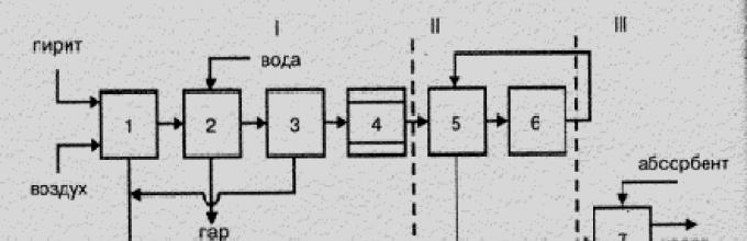
A fundamental (structural) scheme of this production is presented in Fig. 7.1.

Figure 7.1 is a structural scheme for the production of sulfuric acid from the flotation cchedan.
- I - Obtaining a fuggous gas: 1 - Cherdan firing; 2 - gas cooling in the boiler-utilizer; 3 - Total gas purification; 4 - Special gas purification;
- II - Contact: 5 - Heated gas in the heat exchanger; 6 - contacting;
- III - Absorption: 7 - Sulfur oxide absorption (VI) and sulfuric acid formation
7.2. Oxidative firing cchedan
The firing of the creek in the air current represents an irreversible non-catalytic heterogeneous process that flows with heat release through the thermal dissociation of iron disulfide:
and oxidation of dissociation products
what is described by the general equation:
The speed of the oxidative firing process is expressed by the total for heterogeneous processes by the equation
- where To M. - mass transfer coefficient;
- F. - the surface of the contact phase (catalyst);
- D.WITH - Driving power of the process.
Thus, the rate of the roasting process depends on the temperature (through to M), the dispersion of the ribboned cchedan (through f, the concentration of the iron disulfide in the chedane and the oxygen concentration in the air (via DC). In fig. 7.2 The dependence of the roasting rate of the pitchframe from the temperature and dimensions of the particles of the ribbons.

Figure 7.2 - The dependence of the roasting rate of the pitchframe from temperature (A) and particle sizes (b)
The increase in the driving force of the firing process is achieved by flotation of the cchedan, which increases the content of iron disulfide in the raw materials, the enrichment of air with oxygen and the use of excess air during firing to 30% over a stoichiometric amount. In practice, the firing leads at a temperature not higher than 1000 0 s, since the sintering of particles of the rumined raw materials begins behind this limit, which leads to a decrease in the surface of them and makes it difficult to wash the air flow particles.
The furnaces of various designs can be used as the firing reactors: mechanical, dust firing, boiling layer (COP). The flakes of the boiling layer are distinguished by high intensity (up to 10,000 kg / m 2 × day), provide a more complete burnout of iron disulfide (the sulfur content in the firebox does not exceed 0.005 wt. Shares) and temperature control, facilitate the process of heat disposal. The disadvantages of the KS furnaces include the increased content of dust in the gas firing gas, which makes it difficult to clean it. Currently, the KS furnaces completely displaced the furnaces of other types in the production of sulfuric acid from the cchedan.
Firing (oven) gas And the grinding is the oxidative firing products of the pitchfish. The grinding consists of iron (III) oxide, a blank breed and an unbearable residue of the iron disulfide.
The composition of the frying gas depends on the nature of raw materials, composition and excess air during its firing. It includes sulfur oxide (IV), oxygen, nitrogen and a slight amount of sulfur oxide (VI) formed due to the catalytic effect of iron oxide (III). If you do not take into account the content of the latter, the ratio between oxygen and sulfur oxide (IV) in the furnace gas can be expressed by the following equations:
- when firing the cchedan with O2 \u003d 21 - 1.296 with SO 2; (7.2a)
- when burning sulfur with o2 \u003d 21 - with SO 2; (7.2B)
- when burning hydrogen sulfide with O2 \u003d 21 - 1.605С SO 2, (7.2V)
where with SO 2 and C O2 is the content of sulfur oxide (IV) and oxygen in the furnace gas.
In practice, under the firing of the cchedan, the furnace gas contains 13-14% sulfur oxide (IV), 2% oxygen and about 0.1% sulfur oxide (VI). Since in the furnace gas should be an excess of oxygen for the subsequent oxidation of sulfur oxide (IV), its composition is adjusted, diluted with air to the content of sulfur oxide (IV) 7-9% and oxygen 11-9%.
7.3. Cleaning the roasting (furnace) gas
The fuggling gas must be cleaned of dust, sulfuric fog and substances that are catalytic poisons or values \u200b\u200bas side products. In the firing gas, it contains up to 300 g / m 3 of dust, which at the stage of contact clogs the equipment and reduces the activity of the catalyst, as well as the fog of sulfuric acid. In addition, under the cchedan firing, at the same time with the oxidation of iron disulfide, the sulphides of other metals are oxidized in the cheddane. At the same time, arsenic and selenium form gaseous oxides AS 2 O 3 and SEO 2, which go to the firing gas and become catalytic poisons for vanadium contact masses.
Dust and sulfuristic fog are removed from the roasting gas in the process total cleaning gas that includes operations mechanical(coarse) and electric (fine) cleaning. Mechanical purification of gas It is carried out by passing gas through centrifugal dust collectors (cyclones) and fibrous filters that reduce the dust content in a gas to 10-20 g / m 3. Electric gas purification The electrostatic precipitates reduces the content of dust and fog in gas to 0.05-0.1 g / m 3.
After a common cleaning, the burf gas obtained from the cchedan is necessarily exposed. special cleaning To remove dust residues and sulfuristic fog and, mainly, arsenic and selenium compounds that are disposed of. Special gas purification Includes cooling operations to a temperature below the melting point of arsenic oxide (315 0 s) and selenium (340 0 s) in towers, irrigated sequentially 50% (hollow tower) and 20% sulfuric acid (tower with nozzles), removal of the sulfuric fog in wet Electrofilters and final gas dryers in scrubbers irrigated with 95% sulfuric acid. From the system of special purification, the burf gas comes out with a temperature of 140-150 0 C.
Selena oxide (IV), extracted from the firing gas, is restored dissolved in sulfuric acid sulfur oxide (IV) to metallic selenium: which is deposited in sumps.
The new progressive method for cleaning the burden gas is the adsorption of solid absorbers contained in it, for example, silica gel or zeolites. With such dry cleaning, the burgggous gas is not cooled and enters contact at a temperature of about 400 0 s, as a result of which does not require intensive additional heating.
7.3. Contacting sulfur oxide (IV)
The process of contacting the burden gas - Sulfur oxidation reaction IV) to sulfur oxide (VI), is a heterogeneous catalytic, reversible, exothermic reaction and is described by the equation
The thermal effect of the reaction depends on the temperature and is equal to 96.05 kJ at 25 0 s and about 93 kJ at contact temperature. The system "SO 2 - O 2 - SO 3" is characterized by the state of equilibrium in it and the speed of the oxidation process of the sulfur oxide (IV), on which the total result of the process depends.
7.3.1. Equilibrium in the system
The equilibrium constant of the sulfur oxide oxidation reaction (IV) is equal
where: p SO. 3 , p SO. 2 , p O. 2 - equilibrium partial pressure of sulfur oxide (Vi), sulfur oxide (IV) and oxygen, respectively.
The degree of conversion of sulfur oxide (IV) into sulfur oxide (IV) or the degree of contacting, achieved on the catalyst depends on the activity of the catalyst, temperature, pressure, the composition of the invertible gas and the contact time and is described by the equation
where p SO. 3 and p SO. 2 -The values \u200b\u200bas in (7.3).
From equations 7.3 and 7.4 it follows that the equilibrium degree of conversion of sulfur oxide (IV) is associated with the equilibrium constant of the oxidation reaction by the equation
where to P is the equilibrium constant.
The dependence X P on temperature, pressure and content of sulfur oxide (IV) in the firing gas is presented in Table 7.2 and in Fig. 7.3.
Table 7.2 - Dependence X R on temperature, pressure and content of sulfur oxide (IV) in the firing gas
|
Temperature, 0 C * |
Pressure, MPa ** |
|||||||
* With a pressure of 0.1 MPa and the content of sulfur oxide (IV) 0.07 vol. Share.
** at a temperature of 400 0 С and the content of sulfur oxide (IV) 0.07 by peroled.

Figure 7.3 - Dependence of the equilibrium degree of conversion of sulfur oxide (IV) into sulfur oxide (VI) on temperature (A), pressure (b) and sulfur oxide content (IV) in Gaza (B)
From equation 7.5 and table. 7.2 It follows that with a decrease in temperature and an increase in the pressure of the inverted gas, the equilibrium degree of conversion X R increases, which is consistent with the principle of lestelle. At the same time, at a constant temperature and pressure, the equilibrium degree of transformation is the larger than less content Sulfur oxide (IV) in Gaza, that is, the less SO 2: O 2 ratio. This attitude depends on the type of raw material and excess air. This dependence is based on the operation of adjusting the composition of the furnace gas, that is, the dilution of it with air to reduce the content of sulfur oxide (IV).
The degree of oxidation of sulfur oxide (IV) increases with increasing contact time, approaching the equilibrium along the decaying curve (Fig. 1.4). Consequently, contacting time should be such to ensure equilibrium in the system. From fig. 1.4 It follows that the higher the temperature, the more likely an equilibrium is achieved (T 1< t 2), но тем меньше равновесная степень превращения (Х 1 < X 2 при Т 1 > T 2). Thus, the yield of sulfur oxide (VI) depends on both temperature and on the contact time. At the same time, for each contact time, the dependence of the outlet from temperature is expressed by an appropriate curve having a maximum. It is obvious that the envelope of these maxima Line AA (Fig. 1.5) represents the curve of optimal temperatures for different contact times close to an equilibrium curve.
7.3.2. Sulfur oxidation rate (IV)
From the oxidation rate, the amount of sulfur oxide (IV), oxidizing per unit of time and, therefore, the volume of the contact mass, the size of the reactor and other characteristics of the process are depends. The organization of this production stage should provide a higher oxidation rate with the maximum degree of contact achieved in these conditions.
The activation energy of sulfur oxidation oxide (IV) oxygen reaction in sulfur oxide (VI) is very large. Therefore, in the absence of a catalyst, the oxidation reaction even at high temperatures practically does not go. The use of the catalyst allows to reduce the activation energy of the reaction and increase the oxidation rate in accordance with the dependence for the speed constant:
- where k 0 is the rate constant of the chemical reaction;
- E - activation energy, J / mol;
- R is a universal gas constant (8,326 J / mol * K);
- T - Temperature, 0 K.
If without a catalyst, the oxidation reaction 2SO 2 + O 2 \u003d 2 SO 3 proceeds as a third-order response with an activation energy of more than 280 kJ / mol, then in the presence of a vanadium catalyst, its order is reduced to 1.8, and activation energy is 92 kJ / mol.
In the production of sulfuric acid as a catalyst, constant masses are used based on vanadium oxide (V) BAV and SVD brands, named as the initial letters of the elements included in their composition:
Bav (barium, aluminum, vanadium) composition:

SVD (sulfo-vanadato-diatom) composition:

It is assumed that the process of oxidation of sulfur (IV) oxide on these catalysts goes through the diffusion stage of the reagents to the surface of the catalyst, on which the vanadium oxide complex (V) is formed with the activator, sorption of reagents on the catalyst with the latest reaction product desorption (sulfur oxide (VI)) :
The scheme of the vanadium catalyst is presented in Fig. 1.6.

Figure 7.6 - Catalyst Action Scheme: I - diffusion; II - sorption; III - the formation of the complex; IV - desorption
The process of catalysis consists of several consistently occurring elementary acts: diffusion of nitrogen molecules, oxygen and sulfur oxide (IV) to catalyst (I), chemisorption of reagent molecules on the surface of the catalyst (II), chemical interaction of oxygen oxygen and sulfur oxide (IV) on the surface of the catalyst with The transfer of electrons from sulfur oxide molecules to oxygen molecules and the formation of unstable complexes (III), desorption of the resulting sulfur oxide molecules (VI) (IV) and diffusion from the pores and from the surface of the catalyst in the gas phase.
The ignition temperature of the contact vanadium mass is 380-420 0 C and depends on the composition of the input gas, increasing with the decrease in the content of oxygen in it. Contact masses must be in such a state so that the minimum hydraulic resistance of the gas flow and the possibility of diffusion of components through the catalyst layer is ensured. For this, contact masses for reactors with a fixed layer of catalyst are molded in the form of granules, tablets or rings with an average diameter of about 5 mm, and for the boiling layer reactors in the form of balls with a diameter of about 1 mm.
To describe the oxidation rate of sulfur oxide (IV) in sulfur oxide (VI), various kinetic equations are proposed on the vanadium catalyst at the vanadium catalyst. These include equation 1.7, binding the reaction rate with the degree of conversion of sulfur oxide (IV), the constant of the reaction rate, equilibrium constant and gas pressure:
- where H. - equilibrium degree of conversion of sulfur oxide (IV);
- k. - the rate constant of the oxidation reaction;
- but- the initial concentration of sulfur oxide (IV) in Gaza;
- b. - the initial concentration of oxygen in gas;
- R - Gas general pressure;
- To r - Constant equilibrium reaction.
From equations 7.7 and 7.8 it follows that the oxidation rate depends on the reaction rate constant, heavily increasingly with increasing temperature (equation 1.6). However, the equilibrium constant to P decreases to P (equation 1.3) and the member value in equation 1.7 decreases. Thus, the speed of the oxidation process of sulfur oxide (IV) depends on two values \u200b\u200bvarying with increasing temperature in the opposite direction. As a result, the curve of the dependence of the speed of oxidation from temperature should pass through the maximum. From equation 1.7, it also follows that the speed of oxidation of sulfur oxide (IV) is greater than the smaller the degree of conversion of sulfur oxide (IV) into sulfur oxide (VI) achieved in this process. As a result, for each degree of conversion, the dependence of the reaction rate on temperature will be expressed by an individual curve having a maximum. In fig. 7.7 A series of similar curves is presented corresponding to different degrees of transformation for a permanent gas gas. It follows that the speed of oxidation reaction reaches the maximum at certain temperatures, which are the higher, the less this degree of transformation. Line AA, connecting the points of optimal temperatures, is called the line of optimal temperature sequence (lot) and indicates that to achieve the best results, the contact process should be started at high temperature, providing a greater process speed (in practice about 600 0 s), and then to achieve high The degree of conversion to reduce the temperature, withstanding the temperature mode for the lot.

Figure 7.7 - dependence of the oxidation rate of sulfur oxide (IV) on temperature at various degrees of transformation x1
BB and SS lines in fig. 1.7 outlines the area of \u200b\u200bpermissible temperature fluctuations in the real technological process of contacting.
Ensuring a high temperature at the beginning of the oxidation process requires high energy costs to heighten gas entering into contact. Therefore, in practice, the gas temperature at the inlet into the contact apparatus entering the first layer of the catalyst is defined only slightly above the ignition temperature (about 420 0 s). During the reaction, a large amount of heat is distinguished, and since the process in the catalyst layer goes without removal of heat, the gas temperature increases according to adiabat 1, until it reaches the value of 0.8 lots (Fig.7.8). After that, the gas is cooled in the heat exchanger (line A) until the temperature reaches 0.8 lot. After the heat exchanger, the gas is directed to the second catalyst layer and the process according to Adiabat 2, then cooled again and continues the process until the specified degree of contacting X is reached. It is usually enough to have 4-5 layers of contact mass in the contact apparatus. In tab. 7.3 Presents the temperature regime of the 4-layer contact apparatus with an intermediate heat exchange set in accordance with the above principle.

Figure 7.8 - Contacting diagram for 4 layers of CT: 1,2,3,4 - adiabat; A, B, B, G - Cooling Lines
Table 7.3 - Contact Node Temperature Mode
Thus, the contradiction between kinetics and thermodynamics of the oxidation process of sulfur oxide (IV) is quite successfully removed by the design and temperature mode of the contact apparatus. This is achieved by a breakdown of the process at the stage, each of which meets the optimal conditions for the process of contacting the process. Thereby, the initial parameters of the contact mode are determined: the temperature is 400-440 0 s, the pressure is 0.1 MPa, the content of sulfur oxide (IV) in a gas 0.07-0.09 about. Shares, oxygen content in Gaza 0.09-0.11 vol. Share.
Reactors or contact devices for catalytic oxidation of sulfur oxide (IV) are divided into devices with a fixed layer of catalyst (shelf or filtering), in which the contact mass is located in 4-5 layers, and the boiling layer devices. The heat dissipation after passing the gas of each catalyst layer is carried out by introducing a cold gas or air into the apparatus or using the heat exchangers built into the apparatus or separated separately (the principle of recovery).

Figure 7.9 - Constructs of contact machines: A - Contact node: 1 - Contact apparatus, B - Contact apparatus of the boiling layer; 2 - heat exchanger.
The totality of the contact apparatus, heat exchangers and gas pipelines represents the contact node. In fig. 7.9 A contact assembly is presented consisting of a filtering type contact apparatus, and remote heat exchangers, and a boiling layer contact apparatus.
The advantages of contact devices of the boiling layer include:
- the high coefficient of heat transfer from the catalyst is in a state of a boiling layer to the surface of the heat exchanger (10 times more than gas), which allows without overheating to contact the furnace gas with a high content of sulfur oxide (IV) and reduce the ignition temperature of the catalyst;
- insensitivity to dust, brought together with the furnace gas.
7.3.3. Double contacting
The most important task of improving the sulfuric acid production is to increase the degree of contact and reduce sulfur oxide emissions (IV) into the atmosphere. In the usual process, increasing the degree of contacting above 0.98 dollars. Units are inappropriate, as it is associated with a sharp increase in the number and number of layers of contact mass. However, even with this maximum degree of contact, the sulfur oxide (IV) can reach 35-60 tons on modern installations. In addition to significant product losses, it causes the need for complex and expensive treatment facilities for the neutralization of waste gases.
Dual Double Contact Dual Absorption Method (DKDA) It is used to increase the finite degree of contacting and the process of oxidation of sulfur oxide (IV) is carried out in two stages. In the first stage, contacting leads to the degree of conversion not exceeding 0.90-0.92 dollars. After which the sulfur oxide (VI) is separated from the contact gas. The second step of contacting is carried out to the degree of transformation of the sulfur oxide left in gas (IV) of 0.95 dollars remaining in gas. units. The ultimate degree of contact is determined in this case as
- where x 1 is the degree of contact in the first stage;
- X 2 - the degree of contact in the second stage.
The double contact method allows you to increase the degree of contact to 0.995 dollars. units. And for several orders of magnitude to reduce the emission of sulfur oxide (IV) into the atmosphere. In fig. 7.10 shows a double contact diagram using the filter type contact apparatus used in the DC-YES installers.

Figure 7.10 - Double Contact Scheme
7.4. Sulfur oxide absorption (VI)
Sulfur oxide absorption (VI) It is the last stage in the production of sulfuric acid by contact method from the contact gas and turning it into sulfuric acid or oleum. Sulfur oxide absorption (VI) represents a reversible exothermic reaction and is described by the equation
The thermal effect of the reaction depends on the value n and for n \u003d 1 (the formation of sulfuric acid monohydrate) is 92 kJ.
Depending on the quantitative ratio of sulfur oxide (VI) and water, the product can be obtained by various concentrations:
- for n\u003e 1 oleum;
- at n \u003d 1 monohydrate (100% sulfuric acid);
- with N.< 1 water solution Acids (diluted sulfuric acid).
For the sulfur oxide absorption process (VI), the nature of the absorbent is essential. The absorption rate is described by the equation
- where k is the absorption coefficient;
- F - the surface of the phase section "absorbent gas";
- DR is the driving force of the absorption process.
The driving force of the absorption process
Since P * SO 3 is given by the composition of the gas, then the driving force and, therefore, the speed of the absorption process will be the greater, the smaller the equilibrium pressure of sulfur oxide (VI) over the sorbent.
In addition, with a high equilibrium pressure over the sorbent of water vapor P * H2O, due to the interaction of water molecules with sulfur oxide molecules (VI), a pair of sulfuric acid is formed, condensing with the occurrence of a difficult gravy of sulfuric acid fog:
Thus, absorbent with minimal equilibrium pressure above it is sulfur oxide (VI) and water vapor will be the best absorbency. This condition to the maximum extent satisfies the amzeotrop of sulfuric acid with a concentration of 98.3%. The use of sulfuric acid lower concentration leads to the intensive formation of fog, and the use of 100% acid or oleum is to reduce the degree of absorption. In fig. 7.11 The dependence of the sulfur oxide (VI) absorption rate is presented on the concentration of sulfuric acid used as an absorbent.
The absorption of sulfur oxide (VI) is accompanied by the release of a significant amount of heat. Therefore, to ensure the completeness of the absorption of sulfur oxide (VI), the process leads when cooled gas and absorbent to 80 0 s and use devices with a large absorption volume.
In fig. 7.11 Presented the absorption scheme.

Figure 7.11 - diagram of the two-stage process of absorption:
- gas refrigerator;
- olemy absorber;
- monohydrate absorber;
- drying tower;
- refrigerator liquid product;
- collection of oleum;
- collection of monohydrate
Such an absorption scheme allows to obtain, except for contact sulfuric acid with a concentration of 92-93%, also oleum of various concentrations.
7.5. Technological scheme for production of sulfuric acid contact method
Currently, in the production of sulfuric acid and oleum, the contact method is the most common technological scheme using the DC-DC-DC principle (dual contact - double absorption). Part of such a scheme, with the exception of the furnace compartment and separating the overall cleaning of the furnace gas, technologically understated for all circuits, is presented in Fig. 7.12.

Figure 7.12 - Technological scheme for the production of sulfuric acid from the cchedan double contacting DK-yes
- hollow washing tower;
- washing tower with a nozzle;
- moisturizing tower;
- electrostatic filters;
- drying tower;
- turbogazoduvka;
- collection of 75% acid;
- collector of production acid;
- heat exchangers;
- contact apparatus;
- olemy absorber;
- monohydrateq absorber.
- monohydrateq absorber.
Product streams:- I - chilled 98% acid;
- II - production acid for cooling;
- III - chilled oleum or monohydrate;
- IV - production oleum for cooling.
Installation capacity up to 1500 t / day. by monohydrate. Consumable coefficients (per 1 ton of monohydrate): Kolchenan 0.82 tons, water 50 m 3, electricity 82 kW * h.
7.6. Sulfuric acid
The modern industry produces several varieties of sulfuric acid and oleum that differ in concentration and purity (Table 7.4). To reduce the possibility of crystallization of products during transport and storage, as well as in the production itself, standards for commodity varieties, the concentrations of which correspond to eutectic compositions with the lowest crystallization temperatures.
In determining the technical and economic indicators of the sulfuric acid production, the production calculations are carried out, usually, 100% sulfuric acid (monohydrate). To recalculate the mass of oleum on the mass of the monohydrate, the formula is used
Table 7.4 - Commodity varieties of sulfuric acid and oleum
An example of solving the problem
Create the material balance of the drying branch of the fuggous gas. The volume of the fuggous gas V m 3. The composition of the igngious gas (% OB): SO2 - a, O2 - B, N2 - 79. Water vapors in a gas 138 m3 or 110.9 kg. Gas is diluted with air to 7.5% about. SO2. Water pairs are absorbed by sulfuric acid with a mass fraction of ω1 \u003d 94%. Acid is diluted to a mass fraction of ω2 \u003d 93.5%. Gazing from drying branch contains 0.2 g / m3 of water vapor. M SO2 \u003d 64 g / mol, m o2 \u003d 32 g / mol, m n2 \u003d 28 g / mol.
Initial data
V. Obzh.Gaza\u003d 1000 m 3; A - 9.6% (about.) B - 11.4% (about.)
Decision
Calculate the composition of dry fry gas:
V SO 2 \u003d A ∙ V Obzh.Gaza/ 100 \u003d 9.6 ∙ 1000/100 \u003d 276.38 m 3, or M SO 2 \u003d V SO 2 ∙ M SO 2 /22.4 \u003d 789,66 m 3.
Similarly, the volume and mass of oxygen and nitrogen, which are included in the fuggous gas, are calculated, and the data is recorded in the table:
Dry gas volume after dilution with air
Dry air volume to be added to gas
We accept relative air humidity equal to 50% (0.5 pieces of unit) and air temperature 23 ° C. This temperature corresponds to the pressure of a saturated water vapor P \u003d 2786.4 PA (20.9 mm Hg)
The volume of moisture introduced by air:
The composition of the air added to the gas
The total mass of moisture, made by gas and air MH2O, total. \u003d 110.90 + 9.03 \u003d 119.03 kg
Massage of moisture in a gas separating from the drying department
Mass of moisture absorbed by acid
mH2O, right. \u003d MH2O, total. - MH2O, Wow \u003d 119.93 - 0.74 \u003d 119.19 kg
The mass of acids required for gas drying, calculate the monohydrate balance equation in the incoming and leaving acid:
x ω1 h2so4 \u003d (x + mh2 oppogl.) \u003d ω2 H2SO4
0.94x \u003d (x + 119,19) 0,935
0.94x - 0.935x \u003d 111.44
Acid volume (S \u003d 1800 kg / m3)
![]()
Based on the practical data, we accept that 0.3% (about.) SO2 is extracted from the gas, dissolving in H2SO4. The mass of sulfur soluble oxide (IV) SO2 is
mSO2 is satisfied. \u003d VSO2 0.003 \u003d 276.38 0.003 \u003d 0.83 m3 or 2.37 kg
Leaving the drying branch gas contains
|
276,38 – 0,83 = 275,55 |
||
|
2274,1 + 636,8 = 2911,21 |
||
|
328,21 + 169,27 = 497,48 |
||
Mass leaving the drying branch of the acid
mH2SO4 out. \u003d X + MH2O weight. + MSO2 is satisfied. \u003d 22288 + 119,19 + 2.37 \u003d 22409,56
Mass fraction of H2SO4 in this acid

Material Balance of the Drain Gas Drain Process
|
27547,29 |
||||
|
27547,30 |
||||
Contact sulfuric acid reflects the technological scheme in which the feedstock is served by the feedstock (classical scheme) (Fig. 34). This scheme includes four basic stages: 1) Obtaining sulfuric anhydride, 2) Purification of a gas containing a sulfuric anhydride, from impurities, 3) oxidation (on the catalyst) of sulphonic anhydride to sulfur, 4) absorption of sulfur anhydride.
The apparatuses of the first stage of the process include a firing furnace 2, in which sulfur gas is obtained, and dry electrostilifer 5, in which the firing gas is cleaned of dust. On the second stage of the process - the purification of the fuggous gas from impurities, poisonous to the catalyst, gas comes at 300-400 ° C. Gas is purified by washing it colder than gas itself, sulfuric acid. For this purpose, the gas is passed through such devices: washing towers 6 and 7, the first wet electrostilifer 8, the humidifier tower 9 and the second wet electrostilifer 8. In these devices, gas is cleaned from arsenic, sulfur and selenium anhydrides, as well as dust residues. Next, the gas is released from moisture in the drying tower 10 and splashes of sulfuric acid in
The splashotel 11. Both flushing 6 p 7, humidifier 9 and the drying 10 tower are irrigated with circulating sulfuric acid. In the irrigation cycle there are compilations 20, of which sulfuric acid pumps are served by the irrigation of the towers. At the same time, the acid is pre-cooled in the refrigerators 18, where the physical heat of the roasting gas is discharged from the washing towers, and the PZ drying is the heat of the drying sulfuric acid dilution.
The supercharger 12 in this scheme is placed in approximately in the middle of the system; All devices located in front of it are under vacuum, after it - sang pressure. Thus, under pressure, apparatuses are working, providing oxidation of sulfur anhydride to sulfur and absorption of sulfuric anhydrond.
During the oxidation of the sulfury anhydrd, a large amount of heat is highlighted to the CVRNIG, which is used to heat the purified roasting gas entering the contact apparatus 14. Hot sulfuric anhydride through the pipe walls by which it passes in the heat exchanger 13, transmits heat to a colder sulfuric anhydride. The heat exchanger space 13 and entering the contact apparatus 14. Further cooling of the sulfide anhydrond before absorption in oleum 16 and the monohydrate 17 absorbers occurs in an anhydride refrigerator (economizer) 15.
Upon the absorption of the sulfuric anhydride in the absorption unit, a large amount of hepes is released, which is transmitted by circulating acid, irrigating outhic 16 and monohydrate 17 absorbers, and is discharged in refrigerators 19 and 18.
The concentration of oleum and monohydrate increases due to the absorption of all new and new portions of the sulfuric anhydride. The drying acid is all the time is diluted due to the absorption of water vapor vochgic gas vapors. Therefore, to maintain stable concentrations of these acids, there are cycles of dilution with a monohydrate, a monohydrate - drying acid and a cycle of increasing the concentration of drying acid monohydrate. Since the water entered into the monohydrate absorber with drying acid is almost always not enough to obtain the desired concentration of sour!. "Water is added to the collection of monohydrate absorber.
In the first wash tower 6, the acid concentration increases due to absorption from the gas of a small amount of the sulfuric anhydride, which has formed during the cchedan firing in the furnaces. To maintain a stable concentration of washing acid in the first washing tower into its collection, acid is transmitted from the second wash tower. To maintain the necessary concentration of acid in the second wash tower, an acid from the humidifier tower is transmitted to it. If, at the same time, there is not enough water to obtain a standard acid concentration in the first wash tower, it is introduced into the collection or moisturizing or the second washed tower.
On contact sulfuric acid factories, three types of products are usually obtained: oleum, technical sulfuric acid and diluted sulfuric acid from the first wash tower (after selection of selenium acid).
At some plants, the washing acid after purification from impurities is used to dilute the monohydrate or for the preparation of concentrated sulfuric acid by diluting oleum. Sometimes oleum is just diluted with water.
According to the scheme "shown in Fig. 34, a gas containing 4-7.5% S02 is processed. With a lower concentration of S02 heat released in the contact compartment, it lacks for heating the gas entering into contacting (i.e. it is not provided The process of process). At a higher concentration, S02 decreases the degree of contact.
Currently, work is underway on the improvement of the contact sulfuric acid production scheme by the new design of individual stages of this process and the use of more powerful devices providing high performance system performance.
In many plants on drying towers and monohydry absorbs, acid distributors are used, after which the gas contains a minimum spray. In addition, directly in the towers or after them there are devices for separating droplets of fog n splashing. In a number of factories from the technological scheme, a humidifier tower is excluded; Its absence is compensated by an increase in the power of wet electrostilifers or a certain change in the mode of operation of washing towers for more intensive moisturizing gas in the second washing tower, which makes it possible to reduce the cost of electricity to wet cleaning.
In the sulfuric acid industry, intensive and more advanced devices, replacing the wind towers, irrigation refrigerators, centrifugal pumps, etc., are beginning to be widely used, etc. For example, for the separation of S02 from exhaust gases in the production of sulfuric acid. sprayed with gas flow.
As a result of the use of oxygen dius in the firing of raw materials in non-ferrous metallurgy, the concentration of S02 in the exhaust gases increases, which creates the possibility of intensifying the sulfuric acid systems operating on these gases. The use of acid-resistant materials in the manufacture of equipment for the production of sulfuric acid by contacting method can significantly improve product quality and increase the release of reactive sulfuric acid.
The technological process of production of sulfuric acid from the elementary sulfur contact method differs from the process of production from the vscheredan number of features:
special design of furnaces for furnace gas;
increased content of sulfur oxide (IV) in the furnace gas;
lack of pre-purification of the furnace gas. Sulfuric acid production from sulfur according to the dual contact method and double absorption (Fig. 1) consists of several stages:
Air after purification from dust is supplied with a gas-powder in the drying tower, where it is dried by 93-98% sulfuric acid to the moisture content of 0.01% by volume; The dried air enters the sulfur furnace after preheating in one of the heat exchangers of the contact node.
The combustion (combustion) of sulfur is a homogeneous exothermic reaction, which is preceded by a solid sulfur transition to a liquid state and its subsequent evaporation:
S. TB. → S. J. → S. Par
Thus, the combustion process takes place in the gas phase in the stream of pre-dried air and is described by the equation:
S + O. 2 → So. 2 + 297,028 kJ;
For burning sulfur, the furnaces of nozzle and cyclone types are used. In nozzles, the molten sulfur is sprayed in the combustion chamber with compressed air through nozzles, which cannot provide sufficiently mixing sulfur vapor with air and the required combustion rate. In cyclone furnaces, working on the principle of centrifugal dust collectors (cyclones), significantly better mixing of components is achieved and a higher intensity of sulfur burning is ensured than in nozzles.
Then, the gas containing 8.5-9.5% SO 3 is then entered on the first stage of absorption in the absorber, irrigated by oleum and 98% sulfuric acid:
SO. 3 + N. 2 Oh → N. 2 SO. 4 +130,56 kJ;
Next, the gas is purified from sulfuric acid splashes, heats up to 420 ° C and enters the second stage of conversion flowing on two layers of the catalyst. Before the second stage of absorption, the gas is cooled in the economizer and is fed into the absorber of the second stage, irrigated by 98% sulfuric acid, and then after cleaning against splashes, it is thrown into the atmosphere.
The furnace gas for burning sulfur is characterized by a higher content of sulfur oxide (IV) and does not contain a large amount of dust. When burning native sulfur, there are also no compounds of arsenic and selenium, which are catalytic poisons.
This scheme is simple and received the name "short scheme" (Fig. 2).
Fig. 1. The scheme of production of sulfuric acid from sulfur according to the DC-yes method:
1 sulfur furnace; 2-recycler; 3 - Economyzer; 4-launchers; 5, 6-heat exchangers of launchers; 7-pin apparatus; 8-heat exchangers; 9-olemic absorber; 10-drying tower; 11 and 12-acc. The first and second monohydrate absorbers; 13-collections of acid.

Fig.2. Production of sulfuric acid from sulfur (short scheme):
1 - melting chamber for sulfur; 2 - Filter of liquid sulfur; 3 - furnace for burning sulfur; 4 - recycler boiler; 5 - contact apparatus; 6 - oxide-sulfur absorption system (VI); 7- sulfuric acid refrigerators
Existing sulfuric acid production facilities, equipped with a cyclone type furnace, have a capacity of 100 tons of sulfur and more per day. New designs of up to 500 t / days are being developed.
Consumption per 1 ton of monohydrate: sulfur 0.34 tons, water 70 m 3, electricity 85 kWh.
1. Introduction
2. Overall characteristic of the production of sulfuric acid production
3. Raw Sources of Sulfuric Acid
4. A picture of industrial production of sulfuric acid
5. Selection of catalyst
6. Justification of the production method
7. Stages and process chemistry
8. Thermodynamic analysis
9. Kinetics of the oxidation process SO 2
10. Condensation of sulfuric acid
11. Thermodynamic analysis of the condensation process
12. Description of the process scheme
13. Calculation of the material balance
14. Calculation of the heat balance
15. Calculation of the contact apparatus
16. Safety measures during the operation of the production facility
17. List of references
1. Introduction
Sulfuric acid is one of the main multi-dinner products of the chemical industry. It is used in various sectors of the national economy, since it has a complex of special properties that facilitate its technological use. Sulfuric acid does not smoke, does not have colors and odor, at normal temperature is in a liquid state, in concentrated form does not corrodies ferrous metals. At the same time, sulfuric acid refers to the number of strong mineral acids, forms numerous stable salts and cheap.
The technique under sulfuric acid understands systems consisting of sulfur oxide (VI) and water of various composition: P SO 3 · t H 2 O.
Sulfuric acid monohydrate is a colorless oily liquid with a crystallization temperature of 10.37 o C, the boiling point of 296.2 o C and a density of 1.85 t / m 3. With water and sulfur oxide (Vi) it is mixed in all respects, forming hydrates of H 2 SO 4 · H 2 O, H 2 SO 4 · 2N 2 O, H 2 SO 4 · 4N 2 O and compounds with sulfur oxide H 2 SO 4 · SO 3 and H 2 SO 4 · 2SO 3.
These hydrates and compounds with sulfur oxide have different crystallization temperatures and form a series of eutectik. Some of these eutectik have crystallization temperature below zero or close to zero. These features of solutions of sulfuric acid are taken into account when choosing its commodity varieties, which under production and storage conditions should have a low crystallization temperature.
The boiling point of sulfuric acid also depends on its concentration, that is, the composition of the sulfur oxide (VI) - water. With an increase in the concentration of aqueous sulfuric acid, its boiling temperature increases and reaches a maximum of 336.5 ° C at a concentration of 98.3%, which corresponds to the azeotropic composition, and then decreases. The boiling point of oleum with an increase in the content of free sulfur oxide (VI) is reduced from 296.2 o C (boiling point of the monohydrate) to 44.7 ° C corresponding to the boiling point of 100% sulfur oxide (VI).
When heating vapors of sulfuric acid above 400 ° C is subjected to thermal dissociation according to the scheme:
400 ° C 700 ° C
2N 2 SO 4<=> 2N 2 O + 2SO 3<=> 2N 2 O + 2SO 2 + O 2.
Among mineral acids, sulfuric acid in terms of production and consumption ranks first. The world production over the past 25 years has grown more than three times and is currently more than 160 million tons per year.
The applications of sulfuric acid and oleum are very diverse. A significant part of it is used in the production of mineral fertilizers (from 30 to 60%), as well as in the production of dyes (from 2 to 16%), chemical fibers (from 5 to 15%) and metallurgy (from 2 to 3%). It is used for various technological purposes in textile, food and other industries.
2. Overall characteristic of the production of sulfuric acid production
The installation is designed to obtain technical sulfuric acid from hydrogen sulfide gas. The hydrogen sulfide gas comes with hydrotreating installations, gas drying unit, installation of amine regeneration and acidic wastewhere.
Entering commissioning - 1999
The production of production of sulfuric acid is designed for processing 24 thousand tons per year of hydrogen sulfide gas.
The design capacity of the installation in sulfuric acid is 65 thousand tons per year.
The installation project was performed by OJSC "Vnipineft" on the basis of the technology of the Danish company Haldor Tops Aux and OJSC Niuif Moscow.
The Russian part of the installation is represented by a section of the preparation of raw materials, co-A cooker boilers, in, from burning hydrogen sulfide gas, blocks of deaeration of desalted water, neutralization of sulfur dumps and ensuring installation of air to the air.
The Danish side is provided by the WSA unit as part of:
· Contact apparatus (converter);
· Condenser;
· Circulation system and sulfuric acid pumping;
· Air blower system for incineration H 2 S, cooling and dilution of the process gas;
· Silicone oil supply system (acid vapor control unit) in a technological gas in order to reduce SO x emissions into the atmosphere.
3. Raw Sources of Sulfuric Acid
The raw material in the production of sulfuric acid can be elementary sulfur and various seren-containing compounds from which sulfur or sulfur oxide (IV) can be obtained.
Natural deposits of native sulfur sulfur is small, although Clark is equal to 0.1%. Most often, sulfur is in nature in the form of metal sulphides and sulfates metal, and also included in oil, stone coal, natural and associated gases. Significant amounts of sulfur are contained in the form of sulfur oxide in the furnace gas and non-ferrous metallurgy gases and in the form of hydrogen sulfide, released when cleaning combustible gases.
Thus, commodity sources of production of sulfuric acid are quite diverse, although it is still used as raw materials mainly elementary sulfur and iron pram. The limited use of such types of raw materials, as the heat-in-glass gas, copper-smelting gases, is explained by the low concentration of sulfur oxide (IV).
In this case, the fraction of the cchedan in the balance sheet of raw materials decreases, and the share of sulfur increases.
In the general scheme of the sulfuric acid production, the two first stages are essential - preparation of raw materials and its combustion or firing. Their content and hardware design significantly depend on the nature of raw materials, which largely determines the complexity of the technological production of sulfuric acid.
4. Brief description of industrial production methods for sulfuric acid
The production of sulfuric acid from seren-containing raw materials includes several chemical processes in which a change in the degree of oxidation of raw materials and intermediate products occurs. This can be represented as the following scheme:
where I is the stage of obtaining furnace gas (sulfur oxide (IV)),
II - the stage of catalytic oxidation of sulfur oxide (IV) to sulfur oxide (VI) and its absorption (processing in sulfuric acid).
In real production, the processes of preparation of raw materials, furnace gas and other mechanical and physicochemical operations are added to these chemical processes.
In general, sulfuric acid production can be expressed as follows:
Raw materials preparation of raw materials (firing) raw materials
chimney Cleaning Contact Absorption
contact Gas Sulfuric Acid
The specific technological scheme of production depends on the type of raw material, the singularities of the catalytic oxidation of sulfur oxide (IV), the presence or absence of the sulfur oxide absorption stage (VI).
Depending on how the oxidation process of SO 2 VS 3 is carried out, there are two basic methods of obtaining sulfuric acid.
In the contact method of obtaining sulfuric acid, the oxidation process of SO 2 VSO 3 is carried out on solid catalysts.
The sulfur trioxide is translated into sulfuric acid at the last stage of the process - the absorption of the sulfur trioxide, which is simplified can be represented by the reaction equation:
SO 3 + H 2 ON 2 SO 4
When carrying out a nitrous (tower) process, a nitrogen oxide is used as an oxygen carrier.
The oxidation of sulfur dioxide is carried out in the liquid phase and the final product is sulfuric acid:
SO 3 + N 2 O 3 + N 2 ON 2 SO 4 + 2NO
Currently, the industry mainly use a contact method for producing sulfuric acid, which allows to use devices with greater intensity.
1) The chemical scheme for producing sulfuric acid from the cchedan includes three consecutive stages:
Oxidation of pyrite concentrate oxygen oxygen iron disulfide:
4FeS 2 + 11O 2 \u003d 2F 2 S 3 + 8So 2,
Catalytic oxidation of sulfur oxide (IV) excess oxygen of furnace gas:
2SO 2 + O 2 2SO 3
Sulfur oxide absorption (VI) with sulfuric acid formation:
SO 3 + H 2 ON 2 SO 4
According to the technological design, the production of sulfuric acid from the iron cchedan is the most difficult and consists of several consistently conducted stages.
2) The technological process of production of sulfuric acid from the elementary sulfur contact method differs from the process of production from the cchedan number of features. These include:
– special design furnaces for furnace gas;
- Increased content of sulfur oxide (IV) in the furnace gas;
- Lack of pre-purification of the furnace gas.
Subsequent operations of contacting sulfur oxide (IV) on physico-chemical bases and hardware design are not different from those for the process based on the creek and are usually drawn up according to the DCDA scheme. Gas thermostatization in the contact apparatus in this method is usually carried out by entering cold air between the catalyst layers
3) There is also a method of production of sulfuric acid from hydrogen sulfide, called "wet" catalysis, is that a mixture of sulfur oxide (IV) and water vapor, obtained by burning hydrogen sulfide in air current, is supplied without separation to contact, where sulfur oxide ( IV) oxidized on a solid vanadium catalyst to sulfur oxide (VI). The gas mixture is then cooled in the condenser, where the pairs of sulfuric acid are converted into a liquid product.
Thus, in contrast to the methods of production of sulfuric acid from the pitchdan and sulfur, in the process of wet catalysis there is no special stage of the absorption of sulfur oxide (VI) and the whole process includes only three consecutive stages:
1. Burning hydrogen sulfide:
H 2 S + 1.5O 2 \u003d SO 2 + H 2
with the formation of a mixture of sulfur oxide (IV) and water vapor of equimolecular composition (1: 1).
2. Oxidation of sulfur oxide (IV) to sulfur oxide (VI):
SO 2 + 0,5O 2<=> SO 3.
with the preservation of the equimolecularity of the composition of the sulfur oxide (IV) mixture and water vapor (1: 1).
3. Condensation of vapors and formation of sulfuric acid:
SO 3 + H 2 O<=> H 2 SO 4
thus, the process of wet catalysis is described by the total equation:
H 2 S + 2O 2 \u003d H 2 SO 4
There is a scheme for producing sulfuric acid at elevated pressure. The effect of pressure on the speed of the process is possible to estimate in the kinetic region, where there is practically no influence of physical factors. Increased pressure affects both the speed of the process and to the equilibrium state. The reaction rate and the product yield with an increase in pressure increases by increasing the current concentrations of SO 2 and O 2 and increase the driving force of the process. But with an increase in pressure, the production costs for the compression of inert nitrogen increase. The temperature in the contact apparatus also increases, because At high pressure and low temperature, the value of the equilibrium constant is not enough compared to the atmospheric pressure scheme.
The large scale of the production of sulfuric acid is particularly sharply putting the problem of its improvement. Here you can allocate the following main directions:
1. Expansion of the raw material base due to the use of exhaust gas boiler electrical electrical plants and various industries.
2. Increase the unit power supply. The increase in power in two or three times reduces the cost of products by 25 to 30%.
3. Intensification of the firing process of raw materials by using oxygen or oxygen air. This reduces the volume of gas passing through the equipment, and increases its performance.
4. Increased pressure in the process, which contributes to an increase in the intensity of the main equipment.
5. The use of new catalysts with increased activity and low ignition temperature.
6. Increasing the concentration of sulfur oxide (IV) in the furnace gas supplied to contacting.
7. Implementing the boiling layer reactors at the firing stages of raw materials and contacting.
8. The use of thermal effects of chemical reactions at all stages of production, including to generate an energy steam.
The most important task in the production of sulfuric acid is to increase the degree of transformation of SO 2 in SO 3. In addition to increasing sulfuric acid performance, this task allows you to solve ecological problems - reduce emissions in environment The harmful component of SO 2.
Many different studies in various areas were conducted to solve this problem: SO 2 absorption, adsorption, research in the change in the design of the contact apparatus.
Essential various designs of contact devices:
Contact apparatus with single contacting: Such a device is characterized by a low degree of conversion of sulfur dioxide into trioxide. The disadvantage of this apparatus is that the gas coming out of the contact apparatus has a high content of sulfur dioxide, which adversely affects an ecological point of view. Using this unit, the exhaust gases must be cleaned of SO 2. To utilize SO 2, there are many different ways: absorption, adsorption, .... This, of course, reduces the amount of SO 2 emissions into the atmosphere, but it increases, in turn, the number of devices in the process, the high content of SO 2 in the gas after the contact apparatus shows a low degree of use of SO 2, so these devices in the production of sulfuric acid are not We use.
Dual contacting apparatus: DC allows you to achieve the same minimum content of SO 2 in exhaust gases as after chemical cleaning. The method is based on the well-known principle of lessel, according to which the removal of one of the components of the reaction mixture shifts equilibrium towards the formation of this component. The essence of the method is to carry out the process of oxidation of sulfur dioxide with the separation of sulfur trioxide in the additional absorber. The DC method allows processing concentrated gases.
Contact apparatus with intermediate cooling. The essence of the method is that the gas entering the contact apparatus, passing through the catalyst layer, falls into the heat exchanger, gas is cooled there, then comes to the next catalyst layer. This method also increases the degree of use of SO 2 and its content in exhaust gases.
5 . Choice of catalyst
The most active catalyst is platinum, but it came out of consumption as a result of the high cost and easy poisoning of impurities of the igngious gas, especially arsenic. Iron oxide is cheap, but with the usual composition of the gas - 7% SO2 and 11% O2, it shows catalytic activity only at temperatures above 625 OS, i.e. When XP 70%, and therefore was used only for the initial oxidation of SO2 until XP 50-60% achieve. The vanadium catalyst is less active than platinum, but cheaper and poisoned by arsenic compounds several thousand times less than platinum; It turned out to be the most rational and only it is used in the production of sulfuric acid. Vanadium contact mass contains an average of 7% V2O5; Activators are oxides alkali metals, usually apply the activator K2O; The carrier serve porous aluminosilicates. Currently, the catalyst is used as a compound SiO2, K and / or CS, V in various proportions. Such a compound turned out to be the most resistant to acid and the most stable. All over the world, its more correct name "Vanadium is containing". Such a catalyst is designed specifically for working with low temperatures, which leads to less emissions into the atmosphere. In addition, such a catalysis is cheaper than potassium / vanadium. Conventional vanadium contact masses are porous granules, tablets or rings.
6. Justification of the production method
Obtaining sulfuric acid from hydrogen sulfide (wet catalysis) on the Perm oil refining plant is a low-tonnage production (65 thousand tons per year). Basically, this production was created in order to reduce emissions of sulfur-containing gases and maximize the raw materials, which in this case is a waste of the oil hydrotreating process.
In addition to using hydrogen sulfide, in the process of obtaining sulfuric acid 3 reactions flow:
H 2 S + 1.5O 2 \u003d SO 2 + H 2
SO 2 + 0,5O 2<=> SO 3.
SO 3 + H 2 O<=> H 2 SO 4
These three reactions proceed with the release of a significant amount of heat, which is used for the various needs of the production of sulfuric acid production and for various purposes of the enterprise: the preparation of the steam, which is used in this production, obtaining a high-pressure pair that use other installations, heated air entering boilers For burning hydrogen sulfide and in the contact apparatus.
The advantage of obtaining sulfuric acid from hydrogen sulfide is that this process also uses hydrogen sulfide, and sulfur dioxide, which significantly reduces emissions into the atmosphere, during a process consisting of 3 reactions, use low temperature and atmospheric pressure, which significantly reduces Energy consumption compared to a diagram that applies high pressure. Taking into account the fact that, as a result of the technological process, a large amount of heat is distinguished, the process, due to this, flows in autothermally.
7. Stages and process chemistry
The process of obtaining sulfuric acid by the "wet" catalysis method consists of the following basic stages.
1. Preparation of sulfuric anhydride (SO 2) by burning hydrogen sulfide gas according to the following reaction:
2H 2 S + 3O 2 \u003d 2SO 2 + 2 H 2 O
2. The cooling of flue gases and the heat disposal of the hydrogen sulfide combustion reaction in the recycler boiler to obtain a water vapor.
3. Oxidation of sulfur anhydride to sulfuric anhydride (SO 3) on the vanadium catalyst in the contact apparatus (converter) R-104 according to the following reaction:
2SO 2 + O 3 \u003d 2 SO 3
4. Preparation of sulfuric acid (H 2 SO 4) by condensation in the Condenser WSA U-109 by reaction:
SO 3 + H 2 O \u003d H 2 SO 4
5. To obtain improved sulfuric acid (the content of nitrogen oxides N 2 O 3, less than 0.5 ppm) provides a hydrazine hydrate diagram into a sulfuric acid stream coming into a section of the concentration of sulfuric acid.
Hydrazinsulfate obtained by adding hydrazine to sulfuric acid interacts with nitrosyl inside acid, which causes the content of N 2 O 3 in aware acid:
4noso 3 H + N 2 H 4 · H 2 SO 4 3N2 + 5H 2 SO 4
Excess hydrazine is oxidized to form elementary nitrogen:
N 2 H 4 · H 2 SO 4 + O 2 N2 + 2H 2 O + H 2 SO 4
Chemicalsows of sulfuric acid is expressed by the formula H 2 SO 4. The structural formula of sulfuric acid is as follows:

Relative molecular weight of sulfuric acid - 98.08 kg / kmol.
Anhydrous sulfuric acid contains 100% H 2 SO 4 or 81.63% SO 3 and 18.37% wt. H 2 O. This is a colorless oily liquid that has no odor with a crystallization temperature of 10.37 ºС. The boiling point of anhydrous sulfuric acid at a pressure of 1.01 · 10 5 Pa (760 mm Hg) is 298.2 ºС. The density at 20 ºС is 1830.5 kg / m 3.
With water and sulfur arhydride, sulfuric acid is mixed in any proportions.
In the process of production of sulfuric acid for oxidation of sulfur anhydride, a vanadium catalyst is used in sulfur. It is a porous substance on which an active complex compound is applied containing pentoys of vanadium V 2 O 5.
In this case, the VK-WSA brand catalyst is applied by Haldor Tops.
The ignition temperature of the catalyst 400-430 ºС. At temperatures above 620 ºС, the catalyst activity is quickly reduced, because At the same time, an active complex containing five-pointed vanadium (V 2 O 5) is decomposed, and the structure of the carrier is destroyed, which leads to the destruction of the catalyst and the formation of dust.
The service life of the catalyst is at least 4 years.
8. Thermodynamic analysis
Calculation of the thermal effect of oxidation reaction SO. 2 at SO. 3 :
2SO 2 + O 2 \u003d 2 SO 3
Q \u003d -Δn \u003d 196.6 kJ
The reaction is exothermic - proceeds with heat release.
Δg \u003d ΔH-TΔS \u003d -196,6-298 * 17,66 \u003d -5459,28
SO. 3 :
SO 3 + H 2 O \u003d H 2 SO 4
Q \u003d -Δn \u003d 174,26 kJ
Gibbs energy is significantly less than zero. This means that the reaction is thermodynamically possible.
Table 1
Conclusion: The oxidation reaction SO 2 most fully flows at low temperatures. From this it follows, the oxidation reaction SO 2 is advisable to conduct at low temperatures. Increased pressure, according to the principle of lestelier, affects positively.
9. Kinetics of the process of sulfur dioxide
Reaction rate constant: determined from the Arrhenius equation.
K \u003d K 0 * E (-EA / RT) \u003d 9.3 *10 5 *e (-79000 / 430 * 8,31) \u003d 0.13
EA Energy Activation (79000J / Mol)
R - Gas constant (8.31)
E-temperature
K 0 - pre-exponential factor (9.3 * 10 5 seconds)
Equilibrium

Table 3.
Values \u200b\u200bof the equilibrium degree of conversion at different temperatures
Based on the obtained data of Tables 3 and 4, you can draw the following conclusion: from the point of view of the equilibrium degree of conversion, the process of oxidation of sulfur dioxide must be carried out at a low content of SO 2 in the gas mixture and at low temperatures.
Calculation of the contact time of the gas mixture in the contact apparatus

Table 5.
Gas contact time on the first catalyst layer
τ \u003d σΔτ \u003d 3,188 seconds
Total contact time on the first layer of coat meter \u003d 3,188 seconds.
Table 5.
Gas contact time on the second catalyst layer
τ \u003d ΣΔτ \u003d 6.38 seconds
Calculation of temperature increase
T K \u003d tn + λΔh \u003d 787.26
T n, t to -chanical and finite temperatures, to
λ -Coeffer increase in gas temperature when changing the degree of transformation by 1% in adiabatic conditions
Δh - increasing the degree of transformation
10. Condensation of sulfuric acid
Condensation of a pair of sulfuric acid. In some cases, the gas used to produce sulfuric acid does not contain harmful impurities (arsenic, fluorine). Then it is economically advisable not to expose such a gas washing in special equipment, but to transfer immediately to contacting. It is usually not subjected to drying, therefore such a process is called wet catalysis (for example, obtaining sulfuric acid from hydrogen sulfide). Gas coming to the stage of obtaining sulfuric acid contains SO 3 and H 2 0, and the formation of sulfuric acid does not occur as a result of the absorption of the sulfuric anhydride with acid solutions, but due to the formation of H2SO4 vapors and condensation in the tower with a nozzle or other equipment intended for this process.
The condensation process is more intense (comes at high speed) than the absorption process. In addition, condensation occurs at high temperatures, which facilitates the removal and the use of heat.
With slow cooling of the gas containing SO3 and H 2 O, it is possible to carry out the process of condensation of sulfuric acid vapors without fog. However, the speed of the process at the same time is small and often costly maintaining cooling with greater speed, the formation of a certain amount of fog, and then allocate this fog from the gas mixture. To make the fog easier to deposit in filters, the process lead under such conditions in which large drops are formed. This corresponds to a low value of the resulting suction and a higher irrigation oral acid, than with the usual absorption process ("hot" absorption).
Condensation of acid comes inside glass tubes in which a technological gas that contains a pair of acid is incorporated. Inside glass tubes are spirals that serve as centers for the deposition of sulfuric acid. At the end of each tube, a patron filter is installed (droplet-free), designed to capture sulfuric acid fog. The outer surface of the pipe (intercoux space) is cooled by atmospheric air. Purified gas with a residual sulfuric acid concentration of less than 20 PPM and a temperature of no more than 120 degrees Celsius is reset into the smoke pipe.
About 35% (wt.) Sulfuric acid condenses in volume, while the pairs are converted into a drop of liquid, go into fog and are carried out by the gas flow.
The pressure of steam in the recycler boiler is maintained quite high to the temperature of heat exchanging surfaces. The boiler was above the point of the dew of sulfuric acid (275 ° C).
Non-projected gas from the condenser tower on a lined gas duct through a hydraulic native enters wet electrostilifers. The latter are designed to capture the fog of sulfuric acid fog concentration of 93-94% (mass.). Hydraulic shutter can also serve as a splashler. Purified gas is displayed in the atmosphere. For the initial warm-up of the catalyst in the contact device, a starting heater is used, in which the air heats up due to fuel gas burning.
The use of a capacitor tower in the production of sulfuric acid allows to reduce the number of stages: in place 4 stages the process flows in 3.
1 stage is the burning of hydrogen sulfide in the utilization boilers;
2 Stage is the oxidation of sulfur dioxide in the contact apparatus
3 Stage is the condensation of sulfuric acid vapors in the condenser.
This unit avoids the absorption process, which, in turn, reduces the number of devices
11. Thermodynamic analysis of the condensation process
Calculation of the thermal effect of condensation reaction SO. 3 :
SO 3 + H 2 O \u003d H 2 SO 4
Q \u003d -Δn \u003d 174,26 kJ
The reaction is exothermic - proceed with heat release.
Δg \u003d ΔH-TΔS \u003d -174,26-298 * -288,07 \u003d -86019,12
Gibbs energy is significantly less than zero. This means that the reaction is thermodynamically possible.
H 2 O G \u003d H 2 O
Table 3.
The values \u200b\u200bof thermodynamic quantities
Under standard conditions, the condensation reaction is thermodynamically possible.
The condensation response of sulfuric acid is thermodynamically possible.
Calculation of equilibrium constant
D. G. =- R. * T. * lNKP.
lGKP. =- D. G. / 2.3 * 8.31 * t
Kp. =10 - D. G. / 19,113 * t
Table 5.
Values \u200b\u200bof equilibrium constant depending on temperature
| T, 0 C | T, K. | DG. | Kp. |
| 100 | 373 | -84989,9 | 5,8*10 -4 |
| 200 | 473 | -61056,9 | 0,528 |
| 300 | 573 | -49090,4 | 45,43 |
| 400 | 673 | -37123,9 | 1,043*10 3 |
From table 5, it can be seen that with increasing temperature of the condensation reaction constant of the Kyrgyz Republic drops.
Therefore, the condensation process is advisable to conduct at elevated temperatures.
12. Description of the process scheme
Raw installation comes in two threads:
Hydrogen sulfide gas installations L-24-6, L-24-7, L-24-9, GFU under pressure from 0.35 to 0.6 kg / cm 2;
Sour gas from the regeneration unit of Raox (tit.520) regeneration unit (tit.520) under a pressure of 0.6 kg / cm 2.
At the input of installation, flows are combined and sent to the separator to highlight the liquid phase from it. In the hydrogen sulfide gas pipeline, a mixer for injection of demineralized water for ammonia and MEA absorption is installed before the separator. The consumption of demineralized water is controlled by the Rotameter FI-211.
The liquid phase from the separator in terms of Pos.lisa-320 pump P-207a pump, pumped into the GFC gray-chip unit or the installation of the regeneration of amine and the parties of acidic wastewater.
The hydrogen sulfide pressure on the installation is regulated by the pressure regulator posical-165, the valve of which is installed on the reset pipe H 2 S per torch.
The hydrogen sulfide consumption on the installation is recorded by the device Pos.FIQ-210, the temperature is the device pos.ti-039.
The level in the separator is equipped with a signaling in low and high level Pos.Lisa-320.
From the separator, the hydrogen sulfide comes to burning in the boilers-utilities Ku-A, B, with through the flow regulators. PIC-404 (KU-A), FIC-405 (KU-C), FIC-406 (Ku-C) with valves - USY-401 (Ku-A), USY-402 (KU-C), USY-403 (Ku-C).
The hydrogen sulfide pressure to the boilers-utilizers is regulated by the instruments pos.pisa-401 (ku-a), pos.piza-402 (ku-c), pos.piza-403 (ku-c) with signaling and blocking at minimum pressure in the hydrogen sulfide line At the entrance to the boiler-utilizer.
The burning of hydrogen sulfide in the firebox of the Ku-A boiler-recyclars, B, C to sulfur dioxide (SO 2) occurs in the air current supplied from the BW-131 blower.
Razhihage, heating and output to the MODE-utilizers mode is made on the fuel gas.
The total fuel gas consumption for the installation is recorded by the device Pos.FIQ-632, the pressure of the fuel gas - the device pos.pi-622, temperature - pos .Ti-603.
Fuel gas from the factory network through an electric gaming MO-019 enters the separator of fuel gas, where gas separation from condensate occurs.
The condensate level in the B-211 separator is recorded by the device pos.lisa-999 with a low-level signaling and high levels pos.lisa-999 and blocking at the minimum level.
Condensate from B-211 pump P-211A, automatically at the maximum level of pos.lisa-999 (according to the minimum pump stops) pumped into a gas condensate line from the torch on AT-6.
After the separator, the fuel gas is heated in a vapor heater and is supplied to the boilers-utilizers Ku-A, B, p.
The pressure in the fuel gas line is regulated by the device pos.pica-176, the valve of which is installed on the fuel gas line after.
Fuel gas consumption for each boiler-utilizer is regulated by the instruments PIC.FIC-414 (KU-A), FIC-420 (KU-C), FIC-421 (Ku-C), the valves of which are installed on the corresponding fuel gas lines to the kitlam utilizers.
At the inlet of fuel gas to each recycler boiler, Usy-416 (KU-A), USY-417 (Ku-c), USY-418 (Ku-C), which are included in the boiler-recycler lock system.
There is a blocking for minimal fuel gas pressure on the supply of gas to the nozzles of the boiler-utilizer - pos.psa-416 (Ku-A), PSA-417 (Ku-c), PSA-418 (Ku-C).
The scheme provides for the supply of nitrogen into the fuel gas line for purging the system before the boiler is ignition and when preparing it for repair.
The boiler-utilizer Ku-A, B, C consists of a cyclone firebox, where H 2 S combustion, cooling chambers, steam generation systems by recycling the heat combustion of gases, which include: two-drum (upper and lower) boiler, convective beam and superheater.
Cyclone Flak It consists of a double metal casing formed by two concentrically located cylinders of sheet steel. In the cavity between the trimps circulates hot air, which comes from the inter-guard of the boiler.
Support hot mixture from hydrogen sulfide and air is carried out tangentially through the nozzle device at the front end of the cyclone. The nozzle device is an air channel passing through the cutting of the boiler at an angle of 40 º to the horizontal axis.
The hydrogen sulfide enters the air channel through the holes in the upper wall of the channel with pressure, greater than air pressure, and is mixed with it.
The ignition of the mixture occurs on the cutting cut, burning - inside the cyclone with the rotational motion of the gas flow.
To eliminate the incomplete burning of hydrogen sulfide into the area of \u200b\u200bthe cylonary firebox, a small amount of secondary air is supplied.
The risi of hydrogen sulfide is carried out using a fuel gas entering the furnace through an outstanding device.
Cooling chamber It is formed by the left and right side screens and the rear wall. It mounted three explosive fuses of the membrane type.
Superheater The coil type is located behind the convective beam.
The upper drum with an internal structural device is designed to separate the vapor mixture to the saturated pairs and boiler water, the supply of water of the lower drum and the removal of saturated steam.
The lower drum is designed to supply all the boiler lifting pipes.
Cable lining double. Between the internal and outer sheets of the skin passes air coming for burning. Air pressure between sheath sheets with all boiler modes above gas pressure in the boiler than the gas density of the boiler is ensured.
Outlooking the front wall, the ceiling of the boiler unit and the irrigation of the cyclone firebox is made of refractory concrete.
Air consumption in the fireproof co-A cooker of the Ku-A, C, C is regulated by the instruments poses. Fic-422, respectively, the valves of which are installed on the supply of air to the recycler boiler. The air flow control is included in the cascading sulfide control scheme and maintains the air-hydrogen sulfide ratio in the interval (10-12): 1.
The air pressure at the entrance to the cooker cooler, B, with is registered with the device pos.pisa-420, pis-421, pis-422, respectively. There is alarms and blocking at minimal pressure at the inlet to each recycler boiler.
There is a blocking "Control of the presence of a flame" Pos.BSA-401 (KU-A), pos.BSA-402 (KU-C), pos.BSA-403 (Ku-C), when the boiler-utilizer is stopped.
RazhiriGa Utilizer Ku-A, B, with fuel gas and heating before moving on the burning of hydrogen sulfide, produced with flue gases to the atmosphere through a candle at the outlet of the technological gas out of the boiler to the Sewberry Mo-22 (KU-A), MO-23 (Ku-c), MO-24 (Ku-C).
The temperature of the process gas at the outlet of the KU-A, B, is regulated by the device pos.ticsa-407,408,409 by changing the air flow rate of the hydrogen sulfide, withstanding the predetermined air / gas ratio. If the air / gas ratio is not withstanding and the temperature goes beyond the specified temperature range, then there is a decrease (with an increase in temperature) and an increase (with a decrease in temperature) of hydrogen sulfide consumption into the recycler boiler.
Entering the feed water coming from the pumps of the P-201A, B, C, is carried out in the upper drum of the boiler using the distribution pipe to the immersed hole.
The level of nutrient water in the upper drum of the boiler-utilizer is regulated by the instruments pos.lica-304 (KU-A), LICA-308 (KU-C), LICA-312 (KU-C), which are installed on the feed water lines in Recycler boiler.
The flow rate of nutrient water in the coators-utilizers, B, C is registered with the instruments pos.fi-214,215,216, mounted on the feeding line of the feed water into the boilers - utilizers, respectively.
The pressure of nutrient water at the entrance to the boilers - utilizers is recorded by the instruments pos.pi-115,116,117; Temperature - devices poses. TI-016,019,026 installed at the inlet of nutritious water to the boiler.
The pressure in the boiler-utilizer drum is recorded by the device pos.pia-155 (ku-a), PIA-157 (KU-C), PIA-159 (KU-C) with low and high pressure alarm.
The water level in the upper drum of the boiler is equipped with low and high value alarm; blocking at the minimum and maximum water level post.lsa-306, LSA-307 (Ku-A); LSA-310, LSA-311 (Ku-B); LSA-314, LSA-315 (Ku-C).
The water from the upper drum of the boiler is descended into the lower on five unheated pipes (four of the pure and one of the salt compartments), at the exit of which lattices are installed to prevent steam capture into lower pipes. Then the boiler water from the lower drum enters the evaporative tubes of the radiant screen and the convection beam. A steaming mixture of evaporative tubes enters the top drum jackbar, which ensure the separation of steam from water droplets. The saturated pairs of the top of the drum, passing the separation device, enters the steamer, where it is heated to a temperature of 354 ºС. Steam from the steam-meter enters the RO-40/15 reduction device to reduce the pressure from 34.0-38.5 kgf / cm 2 to 15 kgf / cm 2.
Pressure in the steam system of the Co-A utilizers, B, is regulated by the instrument poses .pica-160, the valve-regulator of which is installed on the pair output lines in Row-40/15.
The water of continuous purge from salt compartments of the upper drum boiler enters the capacity of the purge.
The water of periodic purge during the drainage of boilers also enters the barbarter expander periodic purge.
From tanks, water, cooled in the heat exchanger, where heats the Nutrient Water Deaerator B-201, enters the container. From the tank with the pump, water is pumped out to install Eloou.
Sampling of boiler water from the continuous purge line is carried out through the sampling refrigerator.
The technological gas from the Coo-A boiler-recycler, B, C with a temperature of 530-650 ºС with a volume fraction of SO 2 within 7.5-8.5% enters the mixer X-103, where it is mixed with air and overheated steam.
To dilute the technological gas, air is used, leaving after cooling the capacitor and the injected blower. The drying gas dilution with air is carried out to the volume fraction of SO 2 3.5-4.5%, which is necessary to reduce the point of the acid dew, contained in it, and to increase the oxidation of SO 2 in SO 3.
Steam into the technological gas is supplied from the medium-pressure steam system, pre-heated in an E-163 electrical heater to a temperature of 250-300 ºС, and serves to maintain the humidity of the technological gas in order to ensure sufficient sulfuric acid condensation in the WSA E-109 condenser.
The total flow rate of the technological gas before mixing with air and the steam is recorded by the device Pos.FI-702, the temperature is the device Pos.TiA-1103, the volume fraction of SO 2 is an automatic gas analyzer AIA-501.
Course consumption for mixing is regulated by the device POS.FIC-701, the valve-regulator of which is mounted on the pair line in the electrical heater.
The temperature of the steam after the electric heater is recorded by the device POS.TICA-1101A is regulated by the electrical heater control system.
Mixing air consumption is regulated by the device POS.FIC-703, the valve of which controls the shovels of the receiving bulleting of the blower.
Air flow devices and steam are connected to a cascading temperature control circuit POS.TICA-1105 of the process gas at the inlet to the contact unit (converter) to maintain a temperature in the range of 385-430 ºС.
The technological gas from the mixer with a temperature of 400-430 ºС is sent to the contact unit (converter), where there is a catalytic conversion of sulfur dioxide (sulfur arhydride) into the sulfuric anhydride on two layers of the VK-WSA vanadium catalyst with interlayer cooling of the contact gas.
Contact apparatus It is a stainless steel cylindrical apparatus, with two catalyst layers with a height of 820 mm and 1640 mm, respectively.
On the first catalyst layer, about 90-93% SO 2 is converted to SO 3, while the temperature at the outlet of the 1st layer rises to 500-550 ºС. To remove the heat of the reaction, the gas from the 1st layer is cooled in the E-105 riaboyer-gas cooler to a temperature of 380-410 ºС, where the pairs of 62 kgf / cm 2 are produced, then enters the mixer, and from there - on the second catalyst layer. On the second layer, the final conversion of SO 2 in SO 3 occurs, while the outlet temperature rises to 410-430 ºС.
The outlet temperature at the outlet of the gas cooler is regulated by the device POS.TICA-1107, the valve-regulator of which controls the chibers on the gas cooler pipe bundle bypass.
There is a blocking at the maximum gas temperature at the entrance to the contact apparatus - pos.tisa-1104; high gas temperature alarm at the output of the first layer - pos .TiA-1106; Alarm low and high temperature at the outlet of the gas cooler - pos.tica-1107, alarm low and high temperature at the entrance to E-108 - pos .TiA-1109.
The gas after the contact apparatus, pre-cooling in the riaboyler-gas cooler, is sent to the WSA condenser for condensation of sulfuric acid from gas.
The total inlet temperature in the condenser is recorded by the device Pos.TiA-1111 with a signaling at low and high temperatures. There is a blocking at the maximum temperature of Pos.tisa-1110 gas at the inlet to the condenser.
To reduce SO 3 emissions to the atmosphere, together with the spent gas at the WSA condenser output, an acidic pair control unit is provided. The decrease in SO 3 emissions is achieved due to the supply of silicone oil vapor to the gas flow, which serves as centers of sulfuric acid condensation centers and thereby enhances the condensation of the acid in the WSA condenser.
The flow of boiler water into riaboylers-gas cooleders is ensured due to the natural circulation of water from the drum-paoster
Due to the utilization of the heat of the gas flow in the riabolers, steam is produced with a pressure of 62 kgf / cm 2, which from the drum-steam collector is displayed to RO-40/15 through the pressure regulator PICS PICS-902.
The supply of feed water is carried out by the P-161A pump, from Deaerator.
Water level is regulated by the device pos.lica-801 , the valve-regulator of which is mounted on the feed water line from the P-161A pump, B, with a high and low level alarm. There is a blocking at the minimum level of Pos.lsa-802 in the B-162 drum-steamer.
To increase the reliability of the steamer, an additional level gauge is mounted. LIA-803.
To maintain the chemical composition of boiler water (decrease in salt-container), automatic purge from the lower points according to the valves is provided:
· HIC-753 Type "NZ" - in-162;
· HV-791 - E-105;
· HV-792, HV-793, HV-794, HV-795 - E-108.
The purge water from B-162, E-105, E-108 enters the capacity of the purge B-206A, from where, together with the purge water, the Ku-A waste boilers, B, with the E-202 heat exchanger, is reset into the capacity of B-203 and the pump P-203A, in pumped into installment Eloou.
Gas in E-109 comes in two threads.
The surface temperature of the gas inlet pipelines is registered with the instruments pos.TiA-1112, TIA-1113 installed at the input of each flow in E-109, the decrease in the readings of which determines the level of sulfuric acid in E-109 and the possible driving of the tube tube.
The WSA E-109 condenser is a vertical apparatus consisting of 5 modules, each of which contains 720 glass tubes, 6.8 m long and a diameter of 40 mm. Inside the glass tubes are metal spirals that serve as centers for the deposition of sulfuric acid. At the end of each tube, a patron filter is installed (droplet-free), designed to capture sulfuric acid fog. Collection of acid is located at the bottom of the WSA capacitor. E-109 enclosure with acid-resistant brick and tiles.
In the E-109 condenser, the gas rises up inside the glass pipes, on the internal surfaces of which the condensation of sulfuric acid occurs due to air cooling coming from the B-130A blower, in between the tubes.
Purified gas with a residual mass fraction of SO 3 less than 20 PPM and a temperature of no more than 120 ºС is reset into the smoke pipe.
The mass fraction of SO 3 in the purified gas is measured by the AIA-652 device with high content SO 3 signaling.
The temperature of the purified gas is regulated by the device Pos.tica-1115, the valve-regulator of which is mounted on the coolant line into the heaters of the HOV E-133 (reset of air in addition to E-109).
There is a blocking at the maximum gas temperature at the output from E-109 pos.tisa-1116.
The difference between the input and gas output of the E-109 condenser is measured by the device pos.pdi-903.
Air for cooling capacitor WSA E-109 from the atmosphere through the air filter A-133A, in the BW-130A blower, in and is supplied to the intercoupled space E-109 countercurrent of purified gas.
After the E-109 condenser, the cooling air is divided into streams:
· One stream enters the reception of the blower K-131, which delivers air to dilute the technological gas after KU-A, B, C;
· The second stream - the BW-132 blower is supplied to the firebox of the coatakers Ku-A, B, with the burning of hydrogen sulfide;
· Part of the stream is displayed on the reception of the blower K-130A, in to maintain the air temperature on the injection of the blower in the range of 20-35 ºС;
· Excess air is reset to the candle through the heaters of the XOV E-133, utilizing the heat of the cooling air.
The air temperature at the E-109 inlet is regulated by the device Pos. NTIC-1117, a spyber with a pneumatic receipt is installed on the feeding line of the hot air part to receive the blower K-130A, B.
The air temperature after the A-133A filter, is measured by the device POS.TiA-1123.
There is a signaling for low air pressure at the reception of blowers K-130A, in - pos.pia-911,912, respectively.
To prevent leakage of technological gas to the cooling air, the pressure drop is maintained between the cooling air system and the technological gas in the range of 10-41 mm water. The device pos.PDICSA-904, which controls the receiving chi-130a blower seams, c. There is a signaling for low and block on the minimum pressure drop between the cooling air system and the technological gas of the E-109 condenser.
The condensed sulfuric acid from the WSA E-109 condenser flows down the apparatus and is sent to the acid capacity B-120.
To reduce the temperature of the acid coming from E-109, from 270 to 65 ºС in a hot stream of acid, a cold flow of circulating acid from the P-121A pump, c was added.
The acid from the capacity of the B-120 of the P-121 pump is pumped through the E-122 acid plate refrigerator, where it is cooled with recycled water. and heads:
· The main part - as a recycle on mixing with a hot acid of E-109,
· Balance amount of sulfuric acid P-123a pumps, pumped off the installation.
The sulfuric acid temperature at the reception of P-121A pumps, is recorded by the device Pos.TiA-1119 with high temperature signaling. There is a blocking at a maximum temperature pos.tisa-1120 sulfuric acid coming to the reception of the P-121A pumps, c.
The acid level in the B-120 tank is regulated by the instruments pos.lica-804, Lisa-805 , The valve is mounted on the acid pumping line P-123a pumps, in from the installation on the concentration section of the sulfuric acid tit. 75-11 and on the installation of chimspapers TIT.517 PGPN. There are two sulfuric acid pumping pipes in Park 75-11, one of which is in reserve.
The low and high level alarm is provided - pos.lica-804 and blocking at the minimum and maximum level - pos.lisa-805 capacity B-120.
Low and blocking for minimum pressure is provided - pos.pics-906 in the sulfuric acid recycling line.
The mass fraction of circulating acid within 93-98% is controlled by the analyzer POS.AICA-653 and is maintained by automatic water supply from the C-150 tank to the acid circulation line using the USV 1207 shut-off valve.
The water level in the B-150 tank is maintained by the device pos.lia-803, the valve-regulator of which is mounted on the water line in the C-150 tank. There is alarms for low and high levels Pos.LIA-803 in the B-150 tank.
Sulfuric acid consumption from installation is recorded by the device Pos.FIQ-635.
The pressure in the sulfuric acid pumping line is recorded by the device pos.pisa-907. In the case of lowering the pressure in line less than 0.2 kgf / cm 2 in the device POS.PICSA-906 turns on the R-123A reserve pump, in . PBIS is written that the BCA block stops.
To reduce the content of nitrogen oxides (N 2 O 3) in commodity sulfuric acid (less than 0.5 ppm) there is a supply of 64% aqueous hydrazine hydrazine solution with a dosage pump P-124 from the C-160 tank to the sulfuric acid supply pipe to the site Concentration tit.75-11. The finished 64% aqueous solution of hydrazine hydrate enters the installation in the package of 200 liters, from which the pump with a pneumatic reception is pumped into the C-160 tank.
For the collection of emergency spills of acids, the installation is provided by a bellulated reinforced concrete container B-209, in which the sulfuric acid neutralization takes place with a 15% NaOH solution to the pH in the range of 7.0-8.0 by the AA-505 analyzer.
The alkaline solution during neutralization in B-209 is supplied with a gravity of alkali in-208, into which it periodically pumps alkali from the reagent farm.
Before applying alkali in E-209, the P-209 pump on circulation by tank is turned on, and the sulfuric acid is neutralized by slow alkali feeding into the C-209 tank.
It provides for the neutralization of sulfuric acid in B-209 calcined soda. According to the testimony of the analyzer and when checking on a lactium paper pH \u003d 7, the neutralized solution of the P-209 pump is pumped into the PLC in coordination with Uvbosv.
13. Calculation of the material balance
2H 2 S + 3O 2 \u003d 2SO 2 + 2 H 2 O
Gas productivity 1749.8 m 3 / h Degree of conversion H 2 S \u003d 99.9
| Coming | Consumption | |||||||||||
| Mr. | kg | % masses | m3. | % by | colol | Mr. | kg | % masses | m3. | % by | colol | |
| 58,00 | 45,31 | 0,23 | 17,50 | 0,12 | 0,78 | SO2. | 64,00 | 4944,48 | 25,64 | 1730,57 | 12,53 | 77,26 |
| 34,00 | 2629,39 | 13,63 | 1732,30 | 11,82 | 77,33 | H2O. | 18,00 | 1460,94 | 7,57 | 1818,06 | 13,16 | 81,16 |
| 32,00 | 3870,85 | 20,07 | 2709,59 | 18,49 | 120,96 | N2. | 28,00 | 12741,53 | 66,06 | 10193,23 | 73,79 | 455,05 |
| 28,00 | 12741,53 | 66,06 | 10193,23 | 69,57 | 455,05 | H2s. | 34,00 | 2,63 | 0,01 | 1,73 | 0,01 | 0,08 |
| - | 19287,07 | 100,00 | 14652,62 | 100,00 | 654,13 | CO2. | 44,00 | 137,48 | 0,71 | 69,99 | 0,51 | 3,12 |
| ∑ | - | 19287,07 | 100,00 | 13813,58 | 100,00 | 616,68 | ||||||
SO 2 + 0,5O 2<=> SO 3.
The degree of transformation SO 2 \u003d 98.5
| Coming | Consumption | |||||||||||
| Mr. | kg | % masses | m3. | % by | colol | Mr. | kg | % masses | m3. | % by | colol | |
| 64,00 | 4944,48 | 46,03 | 1730,57 | 27,70 | 77,26 | SO3 | 80,00 | 6087,90 | 56,67 | 1704,61 | 31,60 | 76,10 |
| 32,00 | 1217,58 | 11,33 | 852,31 | 13,64 | 38,05 | SO2. | 64,00 | 74,17 | 0,69 | 25,96 | 0,48 | 1,16 |
| 28,00 | 4580,42 | 42,64 | 3664,33 | 58,66 | 163,59 | N2. | 28,00 | 4580,42 | 42,64 | 3664,33 | 67,92 | 163,59 |
| - | 10742,48 | 100,00 | 6247,21 | 100,00 | 278,89 | ∑ | - | 10742,48 | 100,00 | 5394,90 | 100,00 | 240,84 |
SO 3 + H 2 O \u003d H 2 SO 4
The degree of conversion SO 3 \u003d 99.5%
| Coming | Consumption | ||||||||||||
| Mr. | kg | % masses | m3. | % by | colol | Mr. | kg | % masses | m3. | % by | colol | ||
| SO3 | 80,00 | 6087,90 | 80,90 | 1704,61 | 49,75 | 76,10 | H2SO4. | 98,00 | 7420,39 | 98,61 | 1696,09 | 98,06 | 75,72 |
| H2O. | 18,00 | 1362,93 | 18,11 | 1696,09 | 49,50 | 75,72 | SO3 | 90,00 | 30,44 | 0,40 | 7,58 | 0,44 | 0,34 |
| SO2. | 64,00 | 74,17 | 0,99 | 25,96 | 0,76 | 1,16 | SO2. | 64,00 | 74,17 | 0,99 | 25,96 | 1,50 | 1,16 |
| ∑ | 7524,99 | 100,00 | 3426,66 | 100,00 | 152,98 | ∑ | 7524,99 | 100,00 | 1729,62 | 100,00 | 77,22 | ||
14. Calculation of the heat balance
| Standard Education Education ΔH (298 K, KJ / Mol) | Standard mole heat capacity CP (298 K, J / mol · k) | Specific heat consumption C (KJ / kg to) | |
| SO2. | -296,90 | 39,90 | 0,62 |
| O2. | 0,00 | 29,35 | 0,92 |
| N2. | 0,00 | 29,10 | 1,04 |
| SO3 | -439,00 | 180,00 | 2,25 |
| H2O. | -241,82 | 33,58 | 1,87 |
| H2SO4. | -814,20 | 138,90 | 1,42 |
| C4H10. | -124,70 | 97,78 | 1,69 |
| CO2. | -393,51 | 37,11 |
The thermal balance of the sulfur dioxide oxidation reaction
SO. 2 +1/2 O. 2 = SO. 3
Thermal balance of sulfuric acid condensation reaction
SO. 3 + H. 2 O. = H. 2 SO. 4
Of the calculations of the thermal balance of sulfur dioxide oxidation reactions and the condensation of sulfuric acid, it is clear that during these reactions, a significant amount of heat is allocated, which must be discharged, which is done in the real technological process, to increase the degree of transformation of these reactions, and heat is disposed of for various purposes as Process and enterprises.
15. Calculation of the contact apparatus
Calculation of contact time (given in the kinetics of the oxidation of sulfur dioxide)

τ 1 \u003d σδτ \u003d 3,188 seconds
τ 2 \u003d ΣΔτ \u003d 6.38 seconds
The total time to contact the gas in the contact apparatus is
τ \u003d 3,188 + 6.38 \u003d 9,568

![]() m 2.
m 2.
Calculation of the diameter of the contact apparatus
![]()
The diameter of the contact apparatus is 8 m
16. Safety measures during the operation of the production facility
Security requirements for starting and stopping technological systems and individual types of equipment, withdrawing them to a reserve, finding in reserve and when withdrawing from a reserve to work
The main security requirement when starting and stopping technological equipment is strictly compliance with the starting procedure and stopping the installation set out in Section 6 of these Regulations.
Starting to work or conclusion in the reserve of technological systems is made under the written order of the chief engineer of the PGPN, which indicates the person responsible for the safe conduct of the work and the procedure for organizing launchers or work on the conclusion of the technological system to the reserve.
Starting to work or withdrawal to a reserve of unit equipment is made by order of the installation chief.
Equipment is considered to be a reserve when it is in good condition, fully equipped with control and measuring instruments, alarm and grooves, tested under operating conditions, there is a conclusion of the mechanic installation or workshop on its readiness to operate.
AT winter time All reserve equipment must be warm.
In reserve, equipment should be subjected to daily visual inspection, and dynamic equipment - inspection and running with a set periodicity, but at least 1 time per month. In centrifugal pumps, it is necessary to turn the shaft from hand.
Before starting to work, the technological system should be produced by nitrogen with the control of the residual oxygen content of not more than 0.5% vol. The output of the technological system on the normal technological mode is made according to section 6 of these Regulations.
Before each starting backup pumps, check their condition and position of the shut-off valves on the suction and pumping the pump.
Repair of the hot pump allocated to the reserve should be started only after the body temperature does not exceed 45 ºС.
The R-104 contact apparatus fade from the vapor of sulfuric acid with hot air through the WSA E-109 condenser and further into the smoke tube. For work inside R-104 during stopping, the catalyst and the contact apparatus is cooled by air from the B-132 blower according to the process gas. If the catalyst is not unloaded from the unit, in R-104, an overpressure of air supplied to the machine on the hose jumper is maintained to eliminate the contact of the catalyst with atmospheric air.
Requirements for ensuring explosion safety of the technological process: the accepted boundaries of technological blocks, the values \u200b\u200bof energy indicators and the categories of explosive of blocks, the boundaries of possible destruction during explosions, provided for safety and anti-emergency protection measures
In order to increase safety and limit the mass of products that can expire to the environment as a result of accidents, it is planned to be installed on the installation: high-speed cutting fittings on the lines before pumps, one hundred percent reserve on pumps, pumps of the pumps and ABR; The blocking of heat exchangers has bypass and disconnecting shut-off valves.
The installation is equipped with a distributed process control system (RSU) and an emergency protection system (groove). Light and sound alarm is triggered with the maximum allowable values \u200b\u200bof technological parameters.
On the installation allocated one explosive technological unit - the separation unit.
Evaluation of the explosion hazard of the technological unit is made in accordance with the requirements of the general rules of the explosiveness of chemical, petrochemical and oil refineries "(PB 09-540-03). At the same time, the technological blocks include the devices necessary for the implementation of the main technological process. The blocks include pipelines between devices. Block, as well as reinforcement and instruments of kipia.
Security measures taken in the conduct of the technological process with the implementation of regulatory operations should meet the requirements of regulatory and technical documentation that determines the procedure and conditions for the safe conduct of the production process, personnel actions in emergency situations and repair work. The list of specified technical documentation should be approved by the chief engineer of PGPN.
For the safety of process management, the following activities are performed:
All the equipment and pipelines outdoors having the temperature of the wall over 60 ºС, and in the premises of over 45 ºС, heat insulated;
All equipment and pipelines for protection against static electricity are grounded. Installation has lightning protection;
All moving parts of the mechanisms are fenced;
The B-120 tank is equipped with upper and lower levels.
Mandatory volume of periodic control of the state and parameters of the installation by bypass personnel, as well as its maintenance includes:
· Control of temperatures and pressures in devices for the instruments installed on the ground;
· Check centrifugal pumps for vibration and extraneous noise (for goodness);
· Verification of the tightness of flange compounds, stuffing compacts of shut-off reinforcement and end seals of centrifugal pumps;
· Visual control over the lack of vibration of technological pipelines, especially on pumping pumps;
· Verification of the availability and health of full-time instrumentation;
· Visual control over the presence and in good condition of the fencing of moving parts of the mechanisms, service platforms;
· Visual control over the serviceable state of ventilation systems;
· Visual control over the serviceable state of lifting equipment;
· Checking sampling devices for the absence of product leakage.
In winter, it is additionally necessary to perform the following operations:
· Control over the functioning of heating a ferry of low pressure of apparatus, technological pipelines, instruments of kipia;
· Control over the functioning of heating by the heat-watering water of the instruments of kipia, calorifers of the supply ventilation and technological pipelines;
· Control over the cooling systems of centrifugal pumps, providing a permanent flow of water;
· Control on the permeability of drainage and drainage lines;
· Control over the work of the condensate trap.
It is forbidden to remove the locks in the automatic process control systems.
In case of emergency situations caused by the deviations of the installation parameters from the requirements of the technological regime standards set out in Section 4 of these Regulations, to act according to the "Plan of Localization of Emergency Situations" (Place).
All types of repair work should be carried out in accordance with the annual and monthly "scheduled-warning schedules." Repair work should be carried out in accordance with the requirements of the instructions approved by the Company's Chief Engineer:
Instructions on the procedure for safe carrying out repair work in LUKOIL-PIN LLC (IB-025-003-2005);
Instructions on the procedure for the safe conduct of fireworks at the objects of LLC LUKOIL-PIN (PB-0001-1-2005);
Instructions on the procedure for safe carrying out gas supplies at the objects of LUKOIL-PIN LLC (B-025-002-2005);
Instructions on the procedure for the safe conduct of earthworks on the territory of LLC LUKOIL-PIN (IB-255-004-2005).
Sampling sulfide and drainage separators and containers in gas mask standing back to the wind with a dubler in a gas mask.
Security measures when conducting a technological process, the implementation of regulatory operations
The safe operation of the installation depends on the qualifications of the service personnel, compliance with the safety regulations, fire and gas security, the rules for the technical operation of equipment and communications, compliance with the norms of technological regulations.
The work is allowed by persons who have reached, 180 years of age, which have passed on industrial safety and labor protection, theoretical and practical training for safe techniques and methods of work and surrendered to admission exam independent worknot having medical contraindications.
Everything about the regulatory and technical documentation that determines the procedure and conditions for the safe conduct of the production process, personnel actions in emergency situations and the implementation of repair work, according to the list approved by the chief engineer of PGPN, should be available on the installation, its knowledge and observance by personnel must.
You can only work in good equipment. Constantly monitor the operation of control and automation devices, signaling systems and locks. Strictly withstand all technological mode parameters.
In order to avoid gas acquisition in the production premises, an overweight air support is created in the operator, pumping, transformer substation, electrical switching with multiple air exchange 5.
Pumps are equipped with end seals.
All applications running under pressure are equipped with safety valves. Reset the combustible gases from safety valves is carried out in the torch line; The valve on the flare line during the operation of the installation should be open.
The lighting of the installation is made in accordance with the current standards, the lighting fittings adopted explosion-proof execution.
Fire safety measures when conducting a technological process
Fire safety installation is achieved by the system to prevent the formation of a combustible environment, the prevention of the ignition sources in the combustible environment, the maximum automation of the technological process, the use of fire extinguishing and fire alarms, the use of major building structures with the regulated fire resistance limits and the limits of fire distribution, compliance with the instructions and fire safety rules when operation of buildings, structures and equipment.
The territory of the production facility, as well as production premises and equipment must be kept clean and manner.
Smoking on installation forbidden . Smoking is allowed in a specially reserved place (in coordination with the fire protection), equipped with a born of cigarettes and fire extinguisher.
For tightness of equipment, especially flange compounds and seals, strict control is needed from the service personnel. If the pass is detected, it is necessary to immediately submit water vapor to the skip location and take measures to disable the emergency section or apparatus from work.
In winter, heat the frozen equipment, pipelines, valves are allowed only by steam or hot water. Using open fire is prohibited.
In case of a fire occurred in industrial premises, it is possible to safely evacuate people.
In case of fire or accident at the installation of personnel, not participating in the liquidation of a fire or emergency, evacuated from the territory of the object.
The location of equipment and buildings involves compliance with the corresponding fire gaps.
The installation includes the following fire extinguishes:
5 stationary beaf stems protecting equipment on the outer installation;
Firewood is supplied to the boilers from the network of fire water supply of the enterprise;
For local extinguishing the focus of fire in production premises and steam risers are provided on the outer installation;
The installation is provided with rubber hoses for supplying steam or nitrogen to places of possible sunbathing;
At the installation in the established locations, air-foam and powder fire extinguishers, sandboxes, felt, asbulosite are provided;
Protection of premises by automatic fire alarm;
There are manual fire alarm detectors located outside the building and around the installation perimeter;
Placement of structures, equipment, apparatus, evacuation paths and trips are made taking into account the norms and rules of fire safety and ensure the evacuation of people from buildings and premises before the maximum permissible values \u200b\u200bof hazardous fire factors.
Safe methods for handling pyrophoric sediments
The apparatuses and pipelines after the withdrawal of equipment from work and their release from products should be disappeared with water vapor.
After the release of the apparatus from condensate, the lower fitting or the hatch must be opened and the air sample is taken to analyze the dangerous concentrations of the product vapor (there must be no more than 20% of the lower concentration limit of the NKRP flame distribution limit).
During cleaning the devices, it is necessary to make deposits on the walls of the device. When cleaning the devices, intrinsically safe tools are used. The fulfillment of these works is drawn up the outfit in the prescribed manner.
Pyrophoric sediments extracted from the equipment must be maintained in a wet state to their destruction. Pyrophoric deposits to be stored in the magnifying agent of Augvos.
Ways to neutralize production products for bottles and accidents
With sulfuric acid spilling in the pumping immediately arrange a sandbrave for preventing further spreading of the product. Before cleaning the spilled product and neutralize it with soda or lime.
The removal of sulfuric acid during the release of filters, the repair of acid pumps P-121a, B, P-123A, in or sampling takes place in a bellged container and is neutralized with a 10% alkali solution.
When neutralizing a spilled sulfuric acid of the work in overalls and use the gas mask.
Safe method for removing production products from technological systems and individual types of equipment
When stopping the installation for repair, hydrogen sulfide gas is sent to the torch.
The contact apparatus (converter) R-104 is purged by initially flue gases from the vapor of sulfuric acid through the WSA E-109 capacitor, then hot air along the normal diagram into the smoke pipe.
Sulfuric acid pumped into a commodity park 75-11. The residues of the acid merge into the Bloan capacity of the B-209 and is neutralized with a 10% alkali solution, either fall asleep with soda, (to pH \u003d 7), then pumped into the PLC, as agreed with Uvbosv.
The main potential hazards of the equipment used and pipelines, their responsible components and measures to prevent emergency depressurization of technological systems
The main potential hazards of the technological equipment and pipelines used, their responsible nodes on the installation are:
· The hydrogen sulfide gas processing gas is explosive, fire hazardous and toxic;
· Hydrogen sulfide in the presence of water vapor is a strong corrosive substance affecting metal, a consequence of which there may be depressurization of technological equipment;
· The presence of overpressure (up to 15 kgf / cm 2 - medium pressure steam) and high temperatures in the devices and pipelines creates a threat to the rupture;
· In violation of the mode of operation of the equipment or in cases of its mechanical or corrosion wear, it is possible to depressurize with the occurrence of explosion hazardous and toxic gas concentrations, which can lead to explosions and / or lighting, as well as personnel poisoning;
· Electric shock in case of failure of grounding of current-handing parts of equipment or blasting of electrical insulation;
· The possibility of falling attendants when servicing devices and pipelines located at an altitude of more than one meter, in the absence of a fencing or malfunction;
· The possibility of obtaining thermal burn in the case of contacting the unprotected parts of the body with heated surfaces of the devices and pipelines with impaired insulation;
· The presence of rotating mechanisms creates a threat from them injuries;
· The possibility of depressurization or destruction of devices and pipelines under the influence of external power factors.
Measures to prevent emergency depressurization of technological systems are:
· The heat treatment of the main technological equipment and welded sections of pipelines on media causing corrosion cracking;
· Ensuring the compliance of equipment of pipelines, shut-off valves, safety devices, protective automation systems, signaling the requirements of operating NTD;
· Evaluation of the technical condition of devices, equipment, pipelines and other installation elements;
· Operation of only good equipment and timely execution of planning-preventive repair;
· Timely inspection of equipment;
· Ensuring high-quality repair and cleaning of devices, pipelines;
· Maintaining the technological process without violating the norms of this technological regulation, excluding the output of the parameters of the operation of devices and equipment for critical values.
17. List of literature used
1. Technological Regulations for Sulfuric Acid
2. B.T.Vasiliev, M.I.Thevagina; Sulfuric acid technology. Moscow: Chemistry 1985 386 p.
3. AMKTEPOV; Common chemical technology. Moscow: Higher School, 1990. 520 pp.
4. AMELIN A.G. Production of sulfuric acid. Moscow 1983


