6.2. Electrical resistance of conductors. Changes in conductor resistance depending on temperature and pressure. Superconductivity
From the expression it is clear that the electrical conductivity of conductors, and, consequently, electrical resistivity and resistance depend on the material of the conductor and its condition. The condition of the conductor may vary depending on various external factors pressure (mechanical stress, external forces, compression, stretching, etc., i.e. factors influencing crystal structure metal conductors) and temperature.
The electrical resistance of conductors (resistance) depends on the shape, size, material of the conductor, pressure and temperature:
 . (6.21)
In this case, the dependence of the electrical resistivity of conductors and the resistance of conductors on temperature, as was established experimentally, is described by linear laws:
 ; (6.22)
 , (6.23)
where t and o, R t and R o are, respectively, specific resistances and conductor resistances at t = 0 o C;
 or
or  .
(6.24)
.
(6.24)
From formula (6.23) temperature dependence The resistance of the conductors is determined by the relations:
 ,
(6.25)
,
(6.25)
where T is thermodynamic temperature.
G  The dependence of conductor resistance on temperature is shown in Figure 6.2. A graph of the dependence of the resistivity of metals on the absolute temperature T is presented in Figure 6.3.
WITH  according to classical electron theory metals in an ideal crystal lattice (ideal conductor), electrons move without experiencing electrical resistance ( = 0). From the point of view of modern concepts, the reasons causing the appearance of electrical resistance in metals are foreign impurities and defects in the crystal lattice, as well as the thermal movement of metal atoms, the amplitude of which depends on temperature.
Matthiessen's rule states that the dependence of electrical resistivity on temperature (T) is complex function, which consists of two independent terms:
 ,
(6.26)
,
(6.26)
where ost – residual resistivity;
id – ideal resistivity of the metal, which corresponds to the absolute resistance pure metal and is determined only by the thermal vibrations of atoms.
Based on formulas (6.25), the resistivity of an ideal metal should tend to zero when T 0 (curve 1 in Fig. 6.3). However, resistivity as a function of temperature is the sum of independent terms id and rest. Therefore, due to the presence of impurities and other defects in the crystal lattice of the metal, the resistivity (T) with decreasing temperature tends to some constant final value res (curve 2 in Fig. 6.3). Sometimes passing the minimum, it increases slightly with a further decrease in temperature (curve 3 in Fig. 6.3). The value of residual resistivity depends on the presence of defects in the lattice and the content of impurities, and increases with increasing their concentration. If the number of impurities and defects in the crystal lattice is reduced to a minimum, then there remains one more factor influencing the electrical resistivity of metals - the thermal vibration of atoms, which, according to quantum mechanics, does not stop even at absolute zero temperature. As a result of these vibrations, the lattice ceases to be ideal, and variable forces arise in space, the action of which leads to the scattering of electrons, i.e. emergence of resistance.
Subsequently, it was discovered that the resistance of some metals (Al, Pb, Zn, etc.) and their alloys at low temperatures T (0.1420 K), called critical, characteristic of each substance, abruptly decreases to zero, i.e. e. the metal becomes an absolute conductor. This phenomenon, called superconductivity, was first discovered in 1911 by G. Kamerlingh Onnes for mercury. It was found that at T = 4.2 K, mercury apparently completely loses resistance to electric current. The decrease in resistance occurs very sharply in the interval of several hundredths of a degree. Subsequently, loss of resistance was observed in other pure substances and in many alloys. The transition temperatures to the superconducting state vary, but are always very low.
By exciting an electric current in a ring of superconducting material (for example, using electromagnetic induction), one can observe that its strength does not decrease for several years. This allows us to find the upper limit of the resistivity of superconductors (less than 10 -25 Ohmm), which is much less than the resistivity of copper at low temperatures (10 -12 Ohmm). Therefore, it is assumed that the electrical resistance of superconductors is zero. The resistance before the transition to the superconducting state can be very different. Many of the superconductors room temperature have quite high resistance. The transition to the superconducting state always occurs very abruptly. In pure single crystals it occupies a temperature range less than one thousandth of a degree.
WITH  Among pure substances, aluminum, cadmium, zinc, indium, and gallium exhibit superconductivity. During the research, it turned out that the structure of the crystal lattice, the homogeneity and purity of the material have a significant impact on the nature of the transition to the superconducting state. This can be seen, for example, in Figure 6.4, which shows experimental curves of the transition to the superconducting state of tin of various purities (curve 1 - single-crystalline tin; 2 - polycrystalline tin; 3 - polycrystalline tin with impurities).
In 1914, K. Onnes discovered that the superconducting state is destroyed by a magnetic field when the magnetic induction B exceeds some critical value. The critical value of induction depends on the superconductor material and temperature. The critical field that destroys superconductivity can also be created by the superconducting current itself. Therefore, there is a critical current strength at which superconductivity is destroyed.
In 1933, Meissner and Ochsenfeld discovered that there was no magnetic field inside a superconducting body. When a superconductor located in an external constant magnetic field is cooled, at the moment of transition to the superconducting state, the magnetic field is completely displaced from its volume. This distinguishes a superconductor from an ideal conductor, in which, when the resistivity drops to zero, the induction magnetic field should remain unchanged in volume. The phenomenon of displacement of a magnetic field from the volume of a conductor is called the Meissner effect. The Meissner effect and the absence of electrical resistance are the most important properties of a superconductor.
The absence of a magnetic field in the volume of a conductor allows us to conclude from the general laws of the magnetic field that only a surface current exists in it. It is physically real and therefore occupies some thin layer near the surface. The magnetic field of the current destroys the external magnetic field inside the conductor. In this respect, a superconductor formally behaves like an ideal diamagnetic. However, it is not diamagnetic, since its internal magnetization (magnetization vector) is zero.
Pure substances in which the phenomenon of superconductivity is observed are few in number. Superconductivity is most often observed in alloys. In pure substances, only the Meissner effect occurs, and in alloys, the magnetic field is not completely expelled from the volume (a partial Meissner effect is observed).
Substances in which the full Meissner effect is observed are called superconductors of the first kind, and the partial ones are called superconductors of the second kind.
Superconductors of the second type have circular currents in their volume that create a magnetic field, which, however, does not fill the entire volume, but is distributed in it in the form of individual filaments. As for the resistance, it is equal to zero, as with type I superconductors.
In its own way physical nature superconductivity is the superfluidity of a liquid consisting of electrons. Superfluidity occurs due to the cessation of energy exchange between the superfluid component of the liquid and its other parts, resulting in the disappearance of friction. Essential in this case is the possibility of “condensation” of liquid molecules at the lowest energy level, separated from other levels by a fairly wide energy gap that interaction forces are not able to overcome. This is the reason for turning off interaction. To be able to find many particles at the lowest level, it is necessary that they obey Bose-Einstein statistics, i.e. had an integer spin.
Electrons obey Fermi-Dirac statistics and therefore cannot “condense” at the lowest energy level and form a superfluid electron liquid. The repulsive forces between electrons are largely compensated by the attractive forces of the positive ions of the crystal lattice. However, due to the thermal vibrations of atoms at the nodes of the crystal lattice, an attractive force can arise between the electrons, and they then combine into pairs. Pairs of electrons behave like particles with integer spin, i.e. obey Bose-Einstein statistics. They can condense and form a current of superfluid liquid of electron pairs, which forms a superconducting electric current. Above the lowest energy level there is an energy gap that the electron pair is not able to overcome due to the energy of interaction with other charges, i.e. cannot change its energy state. Therefore there is no electrical resistance.
The possibility of the formation of electron pairs and their superfluidity is explained by quantum theory.
The practical use of superconducting materials (in the windings of superconducting magnets, in computer memory systems, etc.) is difficult due to their low critical temperatures. Currently, ceramic materials that exhibit superconductivity at temperatures above 100 K (high-temperature superconductors) have been discovered and are being actively studied. The phenomenon of superconductivity is explained quantum theory.
The dependence of conductor resistance on temperature and pressure is used in technology to measure temperature (resistance thermometers) and large, rapidly changing pressures (electric strain gauges).
In the SI system, the electrical resistivity of conductors is measured in Ohmm, and resistance is measured in Ohms. One Ohm is the resistance of a conductor in which a direct current of 1A flows at a voltage of 1V.
Electrical conductivity is a quantity determined by the formula
 . (6.27)
The SI unit of conductivity is the siemens. One siemens (1 cm) – conductivity of a circuit section with a resistance of 1 ohm.
In this article we will look at a resistor and its interaction with the voltage and current passing through it. You will learn how to calculate a resistor using special formulas. The article also shows how special resistors can be used as a light and temperature sensor.
The idea of electricity
A beginner should be able to imagine electric current. Even if you understand that electricity consists of electrons moving through a conductor, it is still very difficult to visualize clearly. That's why I offer this simple analogy with a water system that anyone can easily imagine and understand without delving into the laws.
Notice how electric current is similar to the flow of water from a full tank (high voltage) to an empty tank (low voltage). In this simple analogy of water and electric current, a valve is analogous to a current limiting resistor.
From this analogy you can derive some rules that you should remember forever:
- As much current flows into the node, so much flows out of it
- In order for current to flow, there must be different potentials at the ends of the conductor.
- The amount of water in two vessels can be compared to the battery charge. When the water level in different vessels becomes the same, it will stop flowing, and when the battery is discharged, there will be no difference between the electrodes and the current will stop flowing.
- The electric current will increase as the resistance decreases, just as the flow rate of water will increase as the valve resistance decreases.
I could write many more inferences based on this simple analogy, but they are described in Ohm's law below.
Resistor

Resistors can be used to control and limit current, therefore, the main parameter of a resistor is its resistance, which is measured in Omaha. We should not forget about the power of the resistor, which is measured in watts (W), and shows how much energy the resistor can dissipate without overheating and burning out. It is also important to note that resistors are not only used to limit current, they can also be used as a voltage divider to produce a lower voltage from a higher one. Some sensors are based on the fact that resistance varies depending on illumination, temperature or mechanical impact; this is written in detail at the end of the article.
Ohm's law

It is clear that these 3 formulas are derived from the basic formula of Ohm's law, but they must be learned to understand more complex formulas and diagrams. You should be able to understand and imagine the meaning of any of these formulas. For example, the second formula shows that increasing the voltage without changing the resistance will lead to an increase in current. However, increasing the current will not increase the voltage (even though this is mathematically true) because voltage is the potential difference that will create electric current, not the other way around (see the 2 water tank analogy). Formula 3 can be used to calculate the resistance of a current limiting resistor at a known voltage and current. These are just examples to show the importance of this rule. You will learn how to use them yourself after reading the article.
Series and parallel connection of resistors
Understanding the implications of connecting resistors in parallel or in series is very important and will help you understand and simplify circuits using these simple formulas for series and parallel resistance:

In this example circuit, R1 and R2 are connected in parallel, and can be replaced by a single resistor R3 according to the formula:
In the case of 2 resistors connected in parallel, the formula can be written as follows:
In addition to being used to simplify circuits, this formula can be used to create resistor values that you don't have.
Note also that the value of R3 will always be less than that of the other 2 equivalent resistors, since adding parallel resistors provides additional paths
electrical current, reducing the overall resistance of the circuit.

Series-connected resistors can be replaced by a single resistor, the value of which will be equal to the sum of these two, due to the fact that this connection provides additional current resistance. Thus, the equivalent resistance R3 is very simply calculated: R 3 = R 1 + R 2
There are convenient online calculators on the Internet for calculating and connecting resistors.
Current limiting resistor

The most basic role of current limiting resistors is to control the current that will flow through a device or conductor. To understand their operation, let's first look at a simple circuit where the lamp is directly connected to a 9V battery. A lamp, like any other device that consumes electricity to perform a specific task (such as emitting light), has an internal resistance that determines its current consumption. Thus, from now on, any device can be replaced by an equivalent resistance.

Now that the lamp will be considered as a resistor, we can use Ohm's law to calculate the current passing through it. Ohm's law states that the current passing through a resistor is equal to the voltage difference across it divided by the resistance of the resistor: I=V/R or more precisely like this:
I=(V 1 -V 2)/R
where (V 1 -V 2) is the voltage difference before and after the resistor.

Now look at the picture above where a current limiting resistor has been added. It will limit the current going to the lamp, as the name suggests. You can control the amount of current flowing through the lamp simply by selecting correct value R1. A large resistor will reduce the current greatly, while a small resistor will reduce the current less strongly (same as in our water analogy).
Mathematically it will be written like this:
It follows from the formula that the current will decrease if the value of R1 increases. Thus, additional resistance can be used to limit the current. However, it is important to note that this causes the resistor to heat up, and you must correctly calculate its power, which will be discussed later.
You can use the online calculator for .
Resistors as a voltage divider

As the name suggests, resistors can be used as a voltage divider, in other words, they can be used to reduce voltage by dividing it. Formula: ![]()
If both resistors have the same value (R 1 =R 2 =R), then the formula can be written as follows: ![]()
Another common type of divider is when one resistor is connected to ground (0V), as shown in Figure 6B.
Replacing Vb with 0 in formula 6A, we get: ![]()
Nodal analysis
Now, when you start working with electronic circuits, it is important to be able to analyze them and calculate all the necessary voltages, currents and resistances. There are many ways to study electronic circuits, and one of the most common methods is the nodal method, where you simply apply a set of rules and calculate all the necessary variables step by step.
Simplified rules for nodal analysis
Node Definition

A node is any connection point in a chain. Points that are connected to each other, with no other components in between, are treated as a single node. Thus, an infinite number of conductors to one point are considered one node. All points that are grouped into one node have the same voltages.
Branch Definition
A branch is a collection of 1 or more components connected in series, and all components that are connected in series to that circuit are considered as one branch.
All voltages are usually measured relative to ground, which is always 0 volts.
Current always flows from a node with a higher voltage to a node with a lower one.
The voltage at a node can be calculated from the voltage near the node using the formula:
V 1 -V 2 =I 1 *(R 1)
Let's move:
V 2 =V 1 -(I 1 *R 1)
Where V 2 is the desired voltage, V 1 is the reference voltage that is known, I 1 is the current flowing from node 1 to node 2 and R 1 is the resistance between the 2 nodes.
In the same way as in Ohm's law, the branch current can be determined if the voltage of 2 adjacent nodes and the resistance are known:
I 1 =(V 1 -V 2)/R 1
The current input current of a node is equal to the current output current, so it can be written as: I 1 + I 3 =I 2
It is important that you are able to understand the meaning of these simple formulas. For example, in the figure above, current flows from V1 to V2, and therefore the voltage of V2 should be less than V1.
Using the appropriate rules in right moment, you can quickly and easily analyze the diagram and understand it. This skill is achieved through practice and experience.
Calculation of the required resistor power
When purchasing a resistor, you may be asked the question: “What power resistors do you want?” or they can just give 0.25W resistors since they are the most popular.
As long as you are working with resistances greater than 220 ohms and your power supply is providing 9V or less, you can work with 0.125W or 0.25W resistors. But if the voltage is more than 10V or the resistance value is less than 220 ohms, you must calculate the power of the resistor, or it may burn out and ruin the device. To calculate the required resistor power, you must know the voltage across the resistor (V) and the current flowing through it (I):
P=I*V
where current is measured in amperes (A), voltage in volts (V) and P - power dissipation in watts (W)
The photo shows resistors of various powers, they mainly differ in size.

Types of resistors
Resistors can vary from simple variable resistors (potentiometers) to ones that respond to temperature, light and pressure. Some of them will be discussed in this section.
Variable resistor (potentiometer)

The above figure shows a schematic representation of a variable resistor. It is often referred to as a potentiometer because it can be used as a voltage divider.

They vary in size and shape, but they all work the same way. The terminals on the right and left are equivalent to a fixed point (such as Va and Vb in the figure above left), and the middle terminal is the moving part of the potentiometer and is also used to change the resistance ratio of the left and right terminals. Therefore, a potentiometer is a voltage divider that can be set to any voltage from Va to Vb.
Besides, variable resistor can be used as a current limiter by connecting the Vout and Vb pins as in the figure above (right). Imagine how the current will flow through the resistance from the left terminal to the right until it reaches the moving part, and flows along it, while very little current flows to the second part. So you can use a potentiometer to adjust the current of any electronic components, such as a lamp.
LDR (Light Sensing Resistors) and Thermistors
There are many resistor-based sensors that respond to light, temperature or pressure. Most of them are included as part of a voltage divider, which varies depending on the resistance of the resistors, which changes under the influence of external factors.


Photoresistor (LDR)
As you can see in Figure 11A, photoresistors vary in size, but they are all resistors whose resistance decreases when exposed to light and increases in darkness. Unfortunately, photoresistors react rather slowly to changes in light levels and have fairly low accuracy, but are very easy to use and popular. Typically, the resistance of photoresistors can vary from 50 ohms in the sun, to more than 10 megohms in complete darkness.

As we already said, changing the resistance changes the voltage from the divider. The output voltage can be calculated using the formula: 
If we assume that the LDR resistance varies from 10 MΩ to 50 Ω, then V out will be from 0.005V to 4.975V respectively.
A thermistor is similar to a photoresistor, however, thermistors have many more types than photoresistors, for example, a thermistor can be either a negative temperature coefficient (NTC) thermistor, whose resistance decreases with increasing temperature, or a positive temperature coefficient (PTC), whose resistance will increase with increasing temperature. Now thermistors respond to changes in environmental parameters very quickly and accurately.

You can read about determining the resistor value using color coding.
6.2. Electrical resistance of conductors. Changes in conductor resistance depending on temperature and pressure. Superconductivity
From the expression it is clear that the electrical conductivity of conductors, and, consequently, electrical resistivity and resistance depend on the material of the conductor and its condition. The state of the conductor can change depending on various external pressure factors (mechanical stresses, external forces, compression, tension, etc., i.e. factors affecting the crystalline structure of metal conductors) and temperature.
The electrical resistance of conductors (resistance) depends on the shape, size, material of the conductor, pressure and temperature:
In this case, the dependence of the electrical resistivity of conductors and the resistance of conductors on temperature, as was established experimentally, is described by linear laws:
 ; (6.22)
 , (6.23)
where t and o, R t and R o are, respectively, specific resistances and conductor resistances at t = 0 o C;
 or
or
 .
(6.24)
.
(6.24)
From formula (6.23), the temperature dependence of the resistance of conductors is determined by the relations:
![]() ,
(6.25)
,
(6.25)
where T is thermodynamic temperature.
G  The dependence of conductor resistance on temperature is shown in Figure 6.2. A graph of the dependence of the resistivity of metals on the absolute temperature T is presented in Figure 6.3.
WITH  According to the classical electronic theory of metals, in an ideal crystal lattice (ideal conductor), electrons move without experiencing electrical resistance ( = 0). From the point of view of modern concepts, the reasons causing the appearance of electrical resistance in metals are foreign impurities and defects in the crystal lattice, as well as the thermal movement of metal atoms, the amplitude of which depends on temperature.
Matthiessen's rule states that the dependence of electrical resistivity on temperature (T) is a complex function that consists of two independent terms:
 ,
(6.26)
,
(6.26)
where ost – residual resistivity;
id is the ideal resistivity of the metal, which corresponds to the resistance of an absolutely pure metal and is determined only by the thermal vibrations of atoms.
Based on formulas (6.25), the resistivity of an ideal metal should tend to zero when T 0 (curve 1 in Fig. 6.3). However, resistivity as a function of temperature is the sum of independent terms id and rest. Therefore, due to the presence of impurities and other defects in the crystal lattice of the metal, the resistivity (T) with decreasing temperature tends to some constant final value res (curve 2 in Fig. 6.3). Sometimes passing the minimum, it increases slightly with a further decrease in temperature (curve 3 in Fig. 6.3). The value of residual resistivity depends on the presence of defects in the lattice and the content of impurities, and increases with increasing their concentration. If the number of impurities and defects in the crystal lattice is reduced to a minimum, then there remains one more factor influencing the electrical resistivity of metals - the thermal vibration of atoms, which, according to quantum mechanics, does not stop even at absolute zero temperature. As a result of these vibrations, the lattice ceases to be ideal, and variable forces arise in space, the action of which leads to the scattering of electrons, i.e. emergence of resistance.
Subsequently, it was discovered that the resistance of some metals (Al, Pb, Zn, etc.) and their alloys at low temperatures T (0.1420 K), called critical, characteristic of each substance, abruptly decreases to zero, i.e. e. the metal becomes an absolute conductor. This phenomenon, called superconductivity, was first discovered in 1911 by G. Kamerlingh Onnes for mercury. It was found that at T = 4.2 K, mercury apparently completely loses resistance to electric current. The decrease in resistance occurs very sharply in the interval of several hundredths of a degree. Subsequently, loss of resistance was observed in other pure substances and in many alloys. The transition temperatures to the superconducting state vary, but are always very low.
By exciting an electric current in a ring of superconducting material (for example, using electromagnetic induction), one can observe that its strength does not decrease for several years. This allows us to find the upper limit of the resistivity of superconductors (less than 10 -25 Ohmm), which is much less than the resistivity of copper at low temperatures (10 -12 Ohmm). Therefore, it is assumed that the electrical resistance of superconductors is zero. The resistance before the transition to the superconducting state can be very different. Many superconductors have fairly high resistance at room temperature. The transition to the superconducting state always occurs very abruptly. In pure single crystals it occupies a temperature range less than one thousandth of a degree.
WITH  Among pure substances, aluminum, cadmium, zinc, indium, and gallium exhibit superconductivity. During the research, it turned out that the structure of the crystal lattice, the homogeneity and purity of the material have a significant impact on the nature of the transition to the superconducting state. This can be seen, for example, in Figure 6.4, which shows experimental curves of the transition to the superconducting state of tin of various purities (curve 1 - single-crystalline tin; 2 - polycrystalline tin; 3 - polycrystalline tin with impurities).
In 1914, K. Onnes discovered that the superconducting state is destroyed by a magnetic field when the magnetic induction B exceeds some critical value. The critical value of induction depends on the superconductor material and temperature. The critical field that destroys superconductivity can also be created by the superconducting current itself. Therefore, there is a critical current strength at which superconductivity is destroyed.
In 1933, Meissner and Ochsenfeld discovered that there was no magnetic field inside a superconducting body. When a superconductor located in an external constant magnetic field is cooled, at the moment of transition to the superconducting state, the magnetic field is completely displaced from its volume. This distinguishes a superconductor from an ideal conductor, in which, when the resistivity drops to zero, the magnetic field induction in the volume must remain unchanged. The phenomenon of displacement of a magnetic field from the volume of a conductor is called the Meissner effect. The Meissner effect and the absence of electrical resistance are the most important properties of a superconductor.
The absence of a magnetic field in the volume of a conductor allows us to conclude from the general laws of the magnetic field that only a surface current exists in it. It is physically real and therefore occupies some thin layer near the surface. The magnetic field of the current destroys the external magnetic field inside the conductor. In this respect, a superconductor formally behaves like an ideal diamagnetic. However, it is not diamagnetic, since its internal magnetization (magnetization vector) is zero.
Pure substances in which the phenomenon of superconductivity is observed are few in number. Superconductivity is most often observed in alloys. In pure substances, only the Meissner effect occurs, and in alloys, the magnetic field is not completely expelled from the volume (a partial Meissner effect is observed).
Substances in which the full Meissner effect is observed are called superconductors of the first kind, and the partial ones are called superconductors of the second kind.
Superconductors of the second type have circular currents in their volume that create a magnetic field, which, however, does not fill the entire volume, but is distributed in it in the form of individual filaments. As for the resistance, it is equal to zero, as with type I superconductors.
By its physical nature, superconductivity is the superfluidity of a liquid consisting of electrons. Superfluidity occurs due to the cessation of energy exchange between the superfluid component of the liquid and its other parts, resulting in the disappearance of friction. Essential in this case is the possibility of “condensation” of liquid molecules at the lowest energy level, separated from other levels by a fairly wide energy gap that interaction forces are not able to overcome. This is the reason for turning off interaction. To be able to find many particles at the lowest level, it is necessary that they obey Bose-Einstein statistics, i.e. had an integer spin.
Electrons obey Fermi-Dirac statistics and therefore cannot “condense” at the lowest energy level and form a superfluid electron liquid. The repulsive forces between electrons are largely compensated by the attractive forces of the positive ions of the crystal lattice. However, due to the thermal vibrations of atoms at the nodes of the crystal lattice, an attractive force can arise between the electrons, and they then combine into pairs. Pairs of electrons behave like particles with integer spin, i.e. obey Bose-Einstein statistics. They can condense and form a current of superfluid liquid of electron pairs, which forms a superconducting electric current. Above the lowest energy level there is an energy gap that the electron pair is not able to overcome due to the energy of interaction with other charges, i.e. cannot change its energy state. Therefore there is no electrical resistance.
The possibility of the formation of electron pairs and their superfluidity is explained by quantum theory.
The practical use of superconducting materials (in the windings of superconducting magnets, in computer memory systems, etc.) is difficult due to their low critical temperatures. Currently, ceramic materials that exhibit superconductivity at temperatures above 100 K (high-temperature superconductors) have been discovered and are being actively studied. The phenomenon of superconductivity is explained by quantum theory.
The dependence of conductor resistance on temperature and pressure is used in technology to measure temperature (resistance thermometers) and large, rapidly changing pressures (electric strain gauges).
In the SI system, the electrical resistivity of conductors is measured in Ohmm, and resistance is measured in Ohms. One Ohm is the resistance of a conductor in which a direct current of 1A flows at a voltage of 1V.
Electrical conductivity is a quantity determined by the formula
 . (6.27)
The SI unit of conductivity is the siemens. One siemens (1 cm) – conductivity of a circuit section with a resistance of 1 ohm.
When heated, it increases as a result of an increase in the speed of movement of atoms in the conductor material with increasing temperature. The specific resistance of electrolytes and coal when heated, on the contrary, decreases, since in these materials, in addition to increasing the speed of movement of atoms and molecules, the number of free electrons and ions per unit volume increases.
Some alloys, which have more than their constituent metals, almost do not change their resistivity with heating (constantan, manganin, etc.). This is explained by the irregular structure of the alloys and the short mean free path of electrons.
The value showing the relative increase in resistance when the material is heated by 1° (or decreased when cooled by 1°) is called.
If the temperature coefficient is denoted by α, the resistivity at to = 20 o by ρ o, then when the material is heated to a temperature t1, its resistivity p1 = ρ o + αρ o (t1 - to) = ρ o(1 + (α (t1 -to))
and accordingly R1 = Ro (1 + (α (t1 - to))
Temperature coefficient a for copper, aluminum, tungsten is 0.004 1/deg. Therefore, when heated by 100°, their resistance increases by 40%. For iron α = 0.006 1/deg, for brass α = 0.002 1/deg, for fechral α = 0.0001 1/deg, for nichrome α = 0.0002 1/deg, for constantan α = 0.00001 1/deg , for manganin α = 0.00004 1/deg. Coal and electrolytes have a negative temperature coefficient of resistance. Temperature coefficient for most electrolytes it is approximately 0.02 1/deg.
The property of conductors to change their resistance depending on temperature is used in resistance thermometers. By measuring the resistance, the ambient temperature is determined by calculation. Constantan, manganin and other alloys with a very small temperature coefficient of resistance are used for the manufacture of shunts and additional resistances to measuring instruments.
Example 1. How will the resistance Ro of an iron wire change when it is heated to 520°? Temperature coefficient a of iron is 0.006 1/deg. According to the formula R1 = Ro + Ro α (t1 - to) = Ro + Ro 0.006 (520 - 20) = 4Ro, that is, the resistance of the iron wire when heated by 520° will increase 4 times.
Example 2. Aluminum wires at a temperature of -20° have a resistance of 5 ohms. It is necessary to determine their resistance at a temperature of 30°.
R2 = R1 - αR1 (t2 - t1) = 5 + 0.004 x 5 (30 - (-20)) = 6 ohms.
The property of materials to change their electrical resistance when heated or cooled is used to measure temperatures. So, thermal resistance, which are wires made of platinum or pure nickel, fused into quartz, are used to measure temperatures from -200 to +600°. Semiconductor thermal resistances with a large negative coefficient are used for precise definition temperatures in narrower ranges.
 Semiconductor thermal resistances used to measure temperatures are called thermistors.
Thermistors have a high negative temperature coefficient of resistance, that is, when heated, their resistance decreases. made from oxide (subject to oxidation) semiconductor materials consisting of a mixture of two or three metal oxides. The most common are copper-manganese and cobalt-manganese thermistors. The latter are more sensitive to temperature.
Speaking about Ohm's law (§ 1.7), we emphasized the requirement that physical conditions such as temperature and pressure remain constant. The fact is that usually the resistance of conductors depends on temperature:
The resistance of metal wires increases with heating.
For copper wires, every 2.5°C increase in temperature causes an increase in resistance of approximately 1% (one hundredth of their original resistance), or resistance increases by 0.4% for every 1°C increase in temperature. The resistivity values given above correspond to a temperature of 20 °C.
Let, for example, you want to determine the resistivity of copper at a temperature of 45 °.
We know that at 20 °C it was equal to 0.0178 Ohm per 1 m of length with a cross section of 1 mm2. We know that every 2.5 ° it increases by 1%, i.e.
The new temperature exceeds 20°C by 25°C.
This means that the desired resistivity is 10% greater than 0.0178: the resistivity at 45° is equal to Ohm per 1 m with a cross section of 1 mm2.
The dependence of resistance on temperature is often used to determine the temperature of copper wires in electrical machines.
The same dependence of resistance on temperature is used to design electrical thermometers based on measuring the resistance of a piece of wire (often wound in the shape of a spiral) located in the room whose temperature they want to determine.
With this temperature measurement, it is easy to concentrate temperature monitoring in one place different parts rooms (for example, in refrigerators) or various parts of industrial installations.
In this case, you can use a single pointer measuring device by moving the switch to different positions: with each new position, wire spirals, located, for example, on different floors of the refrigerator, are turned on for measurement.
Example 2. The winding resistance of an electric machine at 20 ° C was equal to 60 Ohms. After operating the machine for an hour, the winding resistance increased to 69.6 Ohms. Determine how hot the winding is if for every 10 °C increase in temperature, the resistance increases by 4%. ,
First of all, we are looking for how many percent the resistance has increased:
![]()
Now we easily find that the temperature increased by 40° C, i.e., it became equal to 20 + 40 = 60° C.
Naturally, now the question must arise: does the resistance of electric lamps change when the filament is heated in them? Answer: yes, of course, the filament resistance of a cold lamp is less than the resistance in operating condition. This is what our note made in § 1.7 related to.
We only note that very often the nonlinearity of the characteristic is explained purely electrical phenomena. This is the case in the case of a varistor, the characteristics of which are shown in Fig. 1.14.
In a number of measuring instruments and in special equipment it is often required that their resistance does not change with temperature. For such products, alloys have been developed whose resistance is practically independent of temperature.
Of these alloys, the most commonly used are manganin and constantan.
Many conductors noticeably change their resistance when they are stretched or compressed. This property of conductors has also found important technical application: nowadays pressures and small movements that arise, for example, under loads of beams, rails, machine parts, etc., are often judged by changes in the electrical resistance of specially manufactured elements.
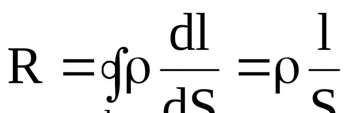
Conductor particles (molecules, atoms, ions) that do not participate in the formation of current are in thermal motion, and particles that form the current are simultaneously in thermal and directional motion under the influence of an electric field. Due to this, numerous collisions occur between particles that form the current and particles that do not participate in its formation, in which the former give up part of the energy they carry from the current source to the latter. The more collisions, the lower the speed of the ordered movement of particles that form the current. As can be seen from the formula I = enνS, a decrease in speed leads to a decrease in current. Scalar quantity, which characterizes the property of a conductor to reduce current, is called conductor resistance. From the formula of Ohm's law, resistance ![]() Ohm - the resistance of the conductor in which a current of strength is obtained 1 a with a voltage at the ends of the conductor of 1 V.
Ohm - the resistance of the conductor in which a current of strength is obtained 1 a with a voltage at the ends of the conductor of 1 V.
The resistance of a conductor depends on its length l, cross-section S and the material, which is characterized by resistivity ![]() The longer the conductor, the more collisions per unit time of particles that form the current with particles that do not participate in its formation, and therefore the greater the resistance of the conductor. The smaller the cross-section of the conductor, the denser the flow of particles that form the current, and the more often they collide with particles that do not participate in its formation, and therefore the greater the resistance of the conductor.
The longer the conductor, the more collisions per unit time of particles that form the current with particles that do not participate in its formation, and therefore the greater the resistance of the conductor. The smaller the cross-section of the conductor, the denser the flow of particles that form the current, and the more often they collide with particles that do not participate in its formation, and therefore the greater the resistance of the conductor.
Under the influence of an electric field, the particles that form the current move accelerated between collisions, increasing their kinetic energy due to the energy of the field. When colliding with particles that do not produce current, they transfer part of their kinetic energy to them. As a result, the internal energy of the conductor increases, which is externally manifested in its heating. Let's consider whether the resistance of a conductor changes when it is heated.

The electrical circuit contains a coil of steel wire (string, Fig. 81, a). Having closed the circuit, we begin to heat the wire. The more we heat it, the less current the ammeter shows. Its decrease occurs because when metals are heated, their resistance increases. Thus, the resistance of a hair of an electric light bulb when it is not lit is approximately 20 ohm, and when it burns (2900° C) - 260 ohm. When a metal is heated, the thermal movement of electrons and the rate of vibration of ions increases. crystal lattice, as a result of this, the number of collisions of current-forming electrons with ions increases. This causes an increase in conductor resistance *. In metals, unfree electrons are very tightly bound to ions, so when metals are heated, the number of free electrons practically does not change.
* (Based on electronic theory, it is impossible to derive an exact law for the dependence of resistance on temperature. This law is established by quantum theory, in which the electron is considered as a particle with wave properties, and the movement of a conduction electron through a metal is a process of propagation of electronic waves, the length of which is determined by the de Broglie relation.)
Experiments show that when the temperature of conductors from various substances For the same number of degrees, their resistance changes differently. For example, if a copper conductor had a resistance 1 ohm, then after heating to 1°C he will have resistance 1.004 ohm, and tungsten - 1.005 ohm. To characterize the dependence of the resistance of a conductor on its temperature, a quantity called the temperature coefficient of resistance was introduced. A scalar quantity measured by the change in resistance of a conductor in 1 ohm, taken at 0° C, from a change in its temperature by 1° C, is called the temperature coefficient of resistance α. So, for tungsten this coefficient is equal to 0.005 deg -1, for copper - 0.004 deg -1. The temperature coefficient of resistance depends on temperature. For metals, it changes little with temperature. For a small temperature range, it is considered constant for a given material.
Let us derive a formula that calculates the resistance of a conductor taking into account its temperature. Let's assume that R0- conductor resistance at 0°С, when heated to 1°C it will increase by αR 0, and when heated to t°- on αRt° and it becomes R = R 0 + αR 0 t°, or
The dependence of the resistance of metals on temperature is taken into account, for example, in the manufacture of spirals for electric heating devices and lamps: the length of the spiral wire and the permissible current are calculated from their resistance in the heated state. The dependence of the resistance of metals on temperature is used in resistance thermometers, which are used to measure the temperature of heat engines, gas turbines, metal in blast furnaces, etc. This thermometer consists of a thin platinum (nickel, iron) spiral wound on a porcelain frame and placed in a protective case. Its ends are connected to an electrical circuit with an ammeter, the scale of which is graduated in degrees of temperature. When the coil heats up, the current in the circuit decreases, this causes the ammeter needle to move, which shows the temperature.
The reciprocal of the resistance of a given section or circuit is called electrical conductivity of the conductor(electrical conductivity). Electrical conductivity of a conductor The greater the conductivity of a conductor, the lower its resistance and the better it conducts current. Name of electrical conductivity unit ![]() Conductor conductivity resistance 1 ohm called Siemens.
Conductor conductivity resistance 1 ohm called Siemens.
As the temperature decreases, the resistance of metals decreases. But there are metals and alloys, the resistance of which, at a low temperature specific for each metal and alloy, sharply decreases and becomes vanishingly small - almost equal to zero (Fig. 81, b). Coming superconductivity- the conductor has practically no resistance, and once the current excited in it exists for a long time, while the conductor is at the superconducting temperature (in one of the experiments, the current was observed for more than a year). When passing a current density through a superconductor 1200 a/mm 2 no release of heat was observed. Monovalent metals, which are the best conductors of current, do not go into the superconducting state until the extreme low temperatures, under which the experiments were carried out. For example, in these experiments copper was cooled to 0.0156°K, gold - up to 0.0204° K. If it were possible to obtain alloys with superconductivity at ordinary temperatures, this would be of great importance for electrical engineering.
According to modern ideas, the main reason for superconductivity is the formation of bound electron pairs. At the temperature of superconductivity, exchange forces begin to act between free electrons, causing the electrons to form bound electron pairs. Such an electron gas of bound electron pairs has different properties than ordinary electron gas - it moves in a superconductor without friction against the nodes of the crystal lattice.
Problem 24. To make the spirals of the electric stove, the workshop received a coil of nichrome wire, on the tag of which it was written: “Weight 8.2 kg, Λ diameter 0.5 mm". Determine how many spirals can be made from this wire if the resistance of the spiral, not included in the network, should be 22 ohms. Density of nichrome 8200 kg/m3.
From here  Where S = πr 2 ; S = 3.14*0.0625 mm 2 ≈ 2*10 -7 m 2.
Wire weight m = ρ 1 V, or m = ρ 1 lS, from here
Answer: n = 1250 spirals.
Problem 25. At a temperature of 20° C, the tungsten filament of a light bulb has a resistance 30 ohm; when you connect it to a DC network with voltage 220v current flows in a spiral 0.6 a. Determine the filament temperature of the light bulb and the strength of the stationary electric field in the lamp filament if its length 550 mm.

The resistance of the spiral when the lamp is burning is determined from the formula of Ohm’s law for a section of the circuit:
Then 
Stationary field strength in a lamp filament
Answer: t 0 Г = 2518°C; E = 400 v/m.
Often employees resist change for no apparent reason. Resistance to change is an attitude or behavior that demonstrates reluctance to implement or support change. First of all, changes affect the attitudes of each employee and cause certain reactions determined by attitude towards changes. One type of psychological protective mechanisms is stereotypes, preventing the correct perception of innovations. The forms of these stereotypes are such that they can provide their bearers with invulnerability from the outside. public opinion:
“we already have this”:
“We won’t be able to do this”:
“this does not solve our main problems
“this needs improvement”:
“not everything is equal here”:
“there are other proposals
The group makes attempts, regardless of changes occurring, to maintain the integrity of attitudes and assessments by any means. Consequently, every external influence causes opposition within the group. This characteristic of organizations is called homeostasis.
Let's list a few more typical phrases:
“patience and labor will grind everything down” (refusal to change);
“let’s start a new life on Monday” (postponing “for later”);
“wouldn’t play the game” (uncertainty);
“a new cry broke the paralysis” (lack of implementation);
“The more paint we waste, the less we believe in fairy tales” (page
tegical inefficiency);
“what the boss doesn’t know, he doesn’t suffer from” (sabotage);
“let’s get back to the real work” (digression).
Types of resistance to organizational change. In order to understand the reasons why people have difficulty accepting change, it is necessary to examine the types of resistance to change in the organization.
Employee resistance to changes in the organization can be in the form of logical rational objections, psychological emotional attitudes, sociological factors and group interests.
Logic resistance- means employees disagree with facts, rational arguments, and logic. Occurs due to the real time and effort required to adapt to changes, including mastering new job responsibilities. These are real costs that employees bear, even though in the long term we are talking about changes that are favorable to them, which means that management needs to compensate them one way or another.
Psychological resistance- usually based on emotions, feelings and attitudes. Is internally “logical” from the point of view of the employee’s attitudes And his feelings about change. Employees may be afraid of the unknown, distrust managers, and feel a threat to their safety. Even if a manager believes such feelings are unjustified, they are very real, which means he must take them into account.
Sociological resistance- the result of the challenge that changes pose to group interests, norms, and values. Since public interests (political coalitions, the values of trade unions and various communities) are a very significant factor in the external environment, management must carefully consider the attitude of various coalitions and groups to change. At the small group level, change jeopardizes the values of friendships and the statuses of team members.
Carrying out changes presupposes that management has prepared to overcome all three types of resistance, especially since its psychological and sociological forms are not something irrational and illogical, but, on the contrary, correspond to the logic of different value systems. In specific work situations, moderate support for change or opposition is most likely.
The task of management is to create an environment of trust in management’s proposals, ensuring a positive perception by employees of most changes and a sense of security. Otherwise, management is forced to use power, too frequent use of which is fraught with their “exhaustion.”
The threat of change may be real or imagined, direct or indirect, significant or insignificant. Regardless of the nature of the change, employees seek to protect themselves from its consequences by using complaints, passive resistance, which can develop into unauthorized absence from the workplace, sabotage and a decrease in work intensity.
Reasons resistance may be threats to employees' needs for safety, social relationships, status, competence, or self-esteem.
Three main reasons for staff resistance to change:
1) uncertainty - occurs when there is insufficient information about the consequences of changes;
2) a sense of loss - occurs when the belief is that innovations reduce decision-making authority, formal or informal power, and access to information;
3) the belief that changes will not bring the expected results.
The main reason for resistance to change is the psychological costs associated with it. Both the company's top executives and line managers may resist changes, but gradually, as new benefits are perceived, this opposition may fade away. Of course, not all changes encounter resistance from employees; some of them are perceived in advance as desirable; other changes may be so slight and imperceptible that resistance, if any, will be very weak. Managers must realize that attitudes toward change are determined primarily by how well the organization's managers have minimized inevitable resistance.
Changes and the feeling of threat emanating from them can trigger a chain reaction effect, i.e. situations where a change directly affecting an individual or a small group of people leads to a direct or indirect reaction of many due to the fact that they are all interested in one or another development of events.
Reasons for resistance to change are usually:
Employees’ feeling of discomfort caused by nature itself
changes when employees show uncertainty about the correctness
technical decisions taken are negatively perceived
the ensuing uncertainty;
Fear of the unknown, threat to the safety of their work;
Techniques for making changes when employees are dissatisfied
Employees feel unfair because someone else benefits from the changes they make;
The feeling that change will lead to personal losses, i.e. lesser degree of satisfaction of any need. Thus, workers may decide that innovations in technology and high levels of automation will lead to layoffs or disruption of social relations, reducing their decision-making power, formal and informal power, access to information, autonomy and attractiveness of the work assigned to them.
The belief that change is not necessary or desirable for the organization. Thus, a manager may decide that a proposed automated management information system is too complex for users or that it will produce the wrong type of information; he may also decide that the problem affects not only his functional area, but also another one - so let them make changes in that department.
Thus, when starting to implement the planned changes in the work of the team, the leader must first determine whether they will cause resistance, what kind of resistance it will be and how to change his line of behavior in order to overcome or eliminate it. Experience shows that most often employee resistance to innovation occurs in cases where:
1) the goals of the changes are not explained to people. Mystery and ambiguity always create uncertainty and anxiety. Fear of the unknown can make employees hostile to something new just as much as the nature of the new thing. In general, people resist general reforms much more than frequent changes in the work process;
2) employees themselves did not take part in planning these changes. People tend to support any reforms if they took part in their preparation - after all, everyone is ready to follow their own recommendations;
3) reforms are motivated by personal reasons. Thus, a manager who asks to help an employee process documents can be sure that others will immediately have questions about what this employee will benefit and why he should be helped. Solidarity is a wonderful trait, but only a few are able to give up something personally and agree to innovations because of this feeling. People need to make sure that this really helps solve the problem, achieve the desired goal, and that it also benefits them;
4) the traditions of the team and their usual style and mode of work are ignored. Many other formal and informal groups will stubbornly resist innovations that threaten their familiar relationships;
5) it seems to subordinates that a mistake was made in preparing the reforms. This feeling is especially intensified if people suspect that there is a threat of a pay cut, demotion, or loss of favor with the manager;
6) perestroika threatens subordinates with a sharp increase in the volume of work. A similar threat arises if the manager did not bother to plan changes far enough in advance;
7) it seems to people that everything is fine as it is (“No need to stick your neck out,” “Why expose your neck to the blow,” “Things have never gone so well for us,” “Initiative is punishable,” etc.);
8) the initiator of reforms is not respected and has no authority. Unfortunately, antipathy towards the author of the project is unconsciously transferred to his proposals, regardless of their true value;
9) when planning reforms, the team does not see the final result (what will this give to the team?);
10) the employee does not know what his personal benefit will be;
11) the subordinate does not feel confident or convinced by the leader;
12) reforms are proposed and implemented in a categorical form, using administrative methods;
13) innovation may lead to staff reductions;
14) people believe that changes can lead to violations of the principle of social justice;
15) the team does not know how much it will cost (costs, effort);
16) the reform does not bring quick results;
17) reforms will bring benefits to a narrow circle of people;
18) the progress of the reform is rarely discussed in the team;
19) there is no atmosphere of trust in the team;
20) under the guise of reform, they actually offer the old, which has not justified itself;
21) within the team there are powerful groups of people who are satisfied with the old, current situation (group egoism);
22) unsuccessful examples of such reform are known;
23) the informal leader of the team is opposed to change.
It is also necessary to talk about the advantages of resistance to change. In certain situations, it leads to management once again carefully analyzing the proposed plans, assessing their adequacy to the real situation. Workers act as part of a system to control the reality of plans and maintain balance. Resistance can help identify specific problem areas, provide managers with information about employees' attitudes on certain issues, and provide employees with an opportunity to vent emotions and encourage them to understand the nature of change.
Methods of overcoming resistance to organizational change are: providing information, participation and involvement, negotiations and agreements, manipulation, coercion.
1) education and communication - open discussion of ideas and activities that will help staff become convinced of the need for change before it is implemented;
2) involving subordinates in decision making. Enables staff who may be resistant to freely express their attitude towards innovation;
3) relief and support - means by which it is easier for staff to fit into the new environment. Additional training and upskilling of staff may be available to enable them to cope with new demands;
4) material and moral incentives. Includes an increase in wages, a commitment not to fire employees, etc.;
5) co-optation. Means giving the person who resists a leading role in making decisions about the introduction of innovations;
6) maneuvering - selective use of information provided to employees, drawing up a clear schedule of activities;
7) gradual transformation, which makes it possible to gradually get used to new conditions;
8) coercion - threat to deprive of work, promotion, professional development, wages, appointment to a new position.